2010 FORD F550 spare tire location
[x] Cancel search: spare tire locationPage 240 of 408
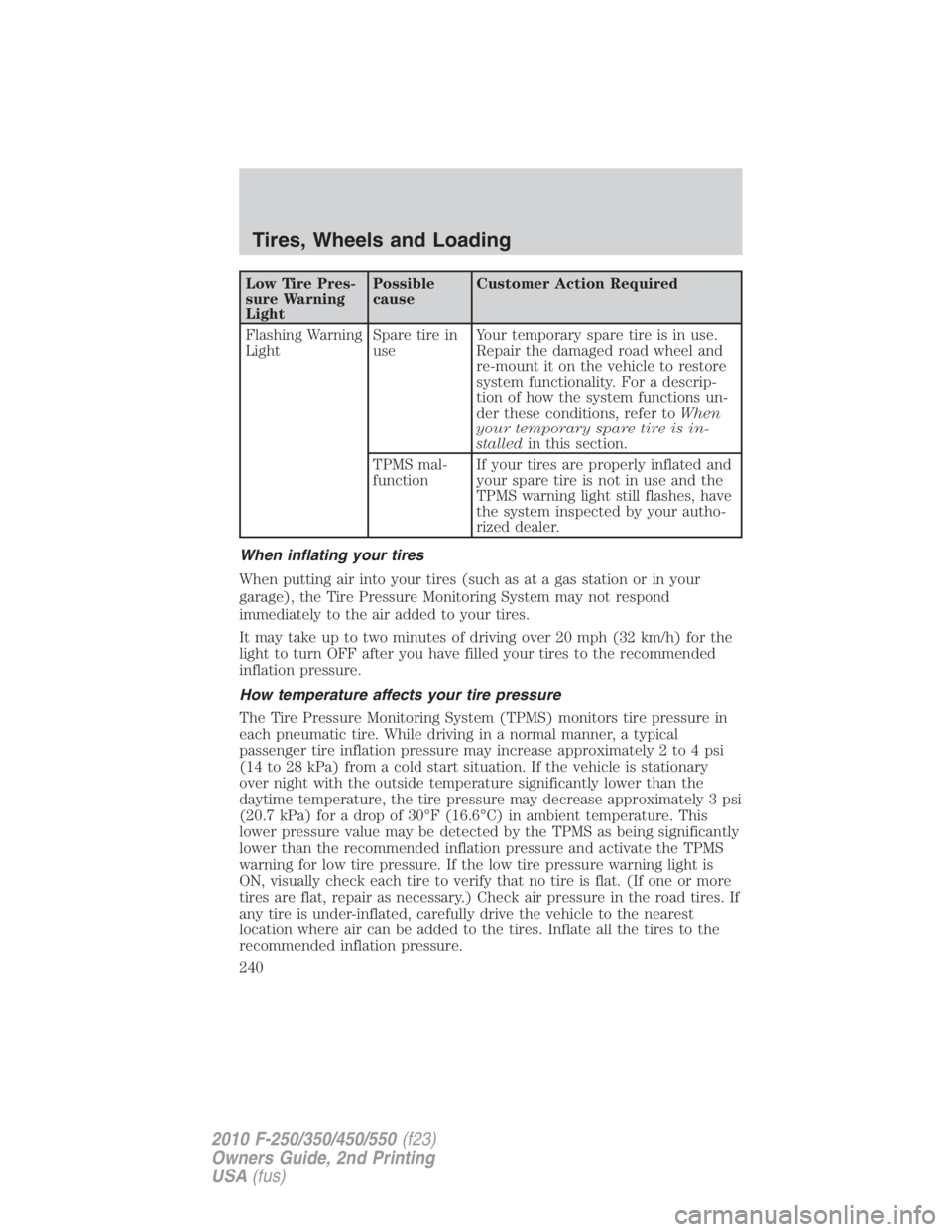
Low Tire Pres-
sure Warning
Light Possible
cause Customer Action Required
Flashing Warning
Light Spare tire in
use Your temporary spare tire is in use.
Repair the damaged road wheel and
re-mount it on the vehicle to restore
system functionality. For a descrip-
tion of how the system functions un-
der these conditions, refer to When
your temporary spare tire is in-
stalled in this section.
TPMS mal-
function If your tires are properly inflated and
your spare tire is not in use and the
TPMS warning light still flashes, have
the system inspected by your autho-
rized dealer.
When inflating your tires
When putting air into your tires (such as at a gas station or in your
garage), the Tire Pressure Monitoring System may not respond
immediately to the air added to your tires.
It may take up to two minutes of driving over 20 mph (32 km/h) for the
light to turn OFF after you have filled your tires to the recommended
inflation pressure.
How temperature affects your tire pressure
The Tire Pressure Monitoring System (TPMS) monitors tire pressure in
each pneumatic tire. While driving in a normal manner, a typical
passenger tire inflation pressure may increase approximately 2 to 4 psi
(14 to 28 kPa) from a cold start situation. If the vehicle is stationary
over night with the outside temperature significantly lower than the
daytime temperature, the tire pressure may decrease approximately 3 psi
(20.7 kPa) for a drop of 30°F (16.6°C) in ambient temperature. This
lower pressure value may be detected by the TPMS as being significantly
lower than the recommended inflation pressure and activate the TPMS
warning for low tire pressure. If the low tire pressure warning light is
ON, visually check each tire to verify that no tire is flat. (If one or more
tires are flat, repair as necessary.) Check air pressure in the road tires. If
any tire is under-inflated, carefully drive the vehicle to the nearest
location where air can be added to the tires. Inflate all the tires to the
recommended inflation pressure.Tires, Wheels and Loading
240
2010 F-250/350/450/550 (f23)
Owners Guide, 2nd Printing
USA (fus)
Page 303 of 408
ROADSIDE ASSISTANCE
Getting roadside assistance
To fully assist you should you have a vehicle concern, Ford Motor
Company offers a complimentary roadside assistance program. This
program is separate from the New Vehicle Limited Warranty. The service
is available:
• 24-hours, seven days a week
• for the coverage period listed on the Roadside Assistance Card
included in your Owner Guide portfolio.
Roadside assistance will cover:
• a flat tire change with a good spare (except vehicles that have been
supplied with a tire inflation kit)
• battery jump start
• lock-out assistance (key replacement cost is the customer’s
responsibility)
• fuel delivery – Independent Service Contractors, if not prohibited by
state, local or municipal law shall deliver up to 2.0 gallons (7.5L) of
gasoline or 5.0 gallons (18.9L) of diesel fuel to a disabled vehicle. Fuel
delivery service is limited to two no-charge occurrences within a
12-month period.
• winch out – available within 100 feet (30.5 meters) of a paved or
county maintained road, no recoveries.
• towing – Ford/Mercury/Lincoln eligible vehicle towed to an authorized
dealer within 35 miles (56 km) of the disablement location or to the
nearest authorized dealer. If a member requests to be towed to an
authorized dealer more than 35 miles (56 km) from the disablement
location, the member shall be responsible for any mileage costs in
excess of 35 miles (56 km).
Trailers shall be covered up to $200 if the disabled eligible vehicle
requires service at the nearest authorized dealer. If the trailer is disabled,
but the towing vehicle is operational, the trailer does not qualify for any
roadside services.
Canadian customers refer to your Customer Information Guide
for information on:
• coverage period
• exact fuel amounts Roadside Emergencies
303
2010 F-250/350/450/550 (f23)
Owners Guide, 2nd Printing
USA (fus)
Page 315 of 408

Fuse/Relay
Location Fuse Amp
Rating Protected Circuits
74 20A** Gasoline engines: Vehicle power
(VPWR): Heated exhaust gas oxygen
sensor, CMS, Mass air flow sensor,
Electronic vapor management valve,
CMCV, Variable cam timing, IMTV
Diesel engine: VPWR: Engine loads
75 5A** Back-up relay coil power
76 20A** Gasoline engines: VPWR: PCM
Diesel engine: VPWR: ECM
77 10A** ABS module logic
* Cartridge fuses ** Mini fuses
CHANGING A FLAT TIRE
If you get a flat tire while driving:
• do not brake heavily.
• gradually decrease the vehicle’s speed.
• hold the steering wheel firmly.
• slowly move to a safe place on the side of the road.
Your vehicle may be equipped with a conventional spare tire that is
different in one or more of the following: type, brand, size, speed rating
and tread design. If this is the case, this dissimilar spare tire is still rated
for your vehicle loads (GAWR and GVWR). Temporary spare tires are not
equipped with Tire Pressure Monitor System (TPMS) sensors if the
system is present.
WARNING: The use of tire sealant may damage your Tire
Pressure Monitoring System (if equipped) and should not be
used.
WARNING: If your vehicle is equipped with a Tire Pressure
Monitoring System, refer to Tire Pressure Monitoring System
(TPMS) in the Tires, Wheels and Loading chapter for more
information. If the tire pressure monitor sensor becomes damaged, it
will no longer function. Roadside Emergencies
315
2010 F-250/350/450/550 (f23)
Owners Guide, 2nd Printing
USA (fus)
Page 316 of 408
Dissimilar spare tire/wheel information
WARNING: Failure to follow these guidelines could result in an
increased risk of loss of vehicle control, injury or death.
If you have a dissimilar spare tire/wheel, then it is intended for
temporary use only. This means that if you need to use it, you should
replace it as soon as possible with a road tire/wheel that is the same size
and type as the road tires and wheels that were originally provided by
Ford. If the dissimilar spare tire or wheel is damaged, it should be
replaced rather than repaired.
A dissimilar spare tire/wheel is defined as a spare tire and/or wheel that
is different in brand, size or appearance from the road tires and wheels
and can be one of three types:
1. T-type mini-spare: This spare tire begins with the letter “T” for tire
size and may have “Temporary Use Only” molded in the sidewall
2. Full-size dissimilar spare with label on wheel: This spare tire has
a label on the wheel that states: “THIS TIRE AND WHEEL FOR
TEMPORARY USE ONLY”
When driving with one of the dissimilar spare tires listed above, do not:
• Exceed 50 mph (80 km/h)
• Load the vehicle beyond maximum vehicle load rating listed on the
Safety Compliance Label
• Use snow chains on the end of the vehicle with the dissimilar spare
tire
• Use more than one dissimilar spare tire at a time
• Use commercial car washing equipment
• Try to repair the dissimilar spare tire
Use of one of the dissimilar spare tires listed above at any one wheel
location can lead to impairment of the following:
• Handling, stability and braking performance
• Comfort and noise
• Ground clearance and parking at curbs
• Winter weather driving capability
• Wet weather driving capability
It is not recommended that the vehicle be operated in 4WD modes with
a temporary emergency spare tire. If 4WD operation is necessary, do not
operate above speeds of 10 mph (16 km/h) or for distances above
50 miles (80 km).Roadside Emergencies
316
2010 F-250/350/450/550 (f23)
Owners Guide, 2nd Printing
USA (fus)
Page 318 of 408
Stopping and securing the vehicle
WARNING: To help prevent the vehicle from moving when you
change a tire, be sure the parking brake is set, then block (in
both directions) the wheel that is diagonally opposite to the tire being
changed.
Refer to the instruction sheet (located in the glove box) for detailed tire
change instructions.
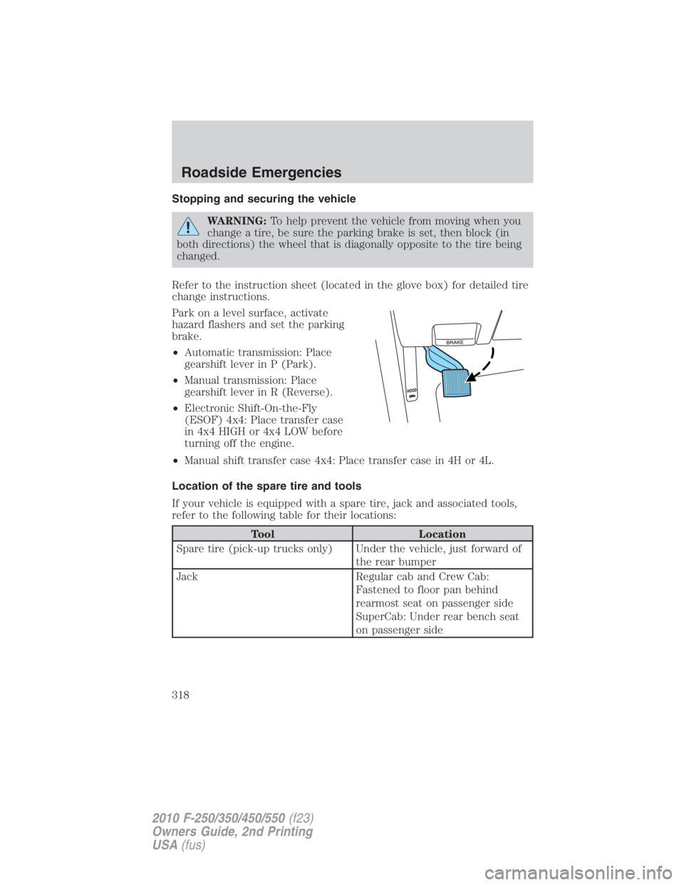
Park on a level surface, activate
hazard flashers and set the parking
brake.
• Automatic transmission: Place
gearshift lever in P (Park).
• Manual transmission: Place
gearshift lever in R (Reverse).
• Electronic Shift-On-the-Fly
(ESOF) 4x4: Place transfer case
in 4x4 HIGH or 4x4 LOW before
turning off the engine.
• Manual shift transfer case 4x4: Place transfer case in 4H or 4L.
Location of the spare tire and tools
If your vehicle is equipped with a spare tire, jack and associated tools,
refer to the following table for their locations:
Tool Location
Spare tire (pick-up trucks only) Under the vehicle, just forward of
the rear bumper
Jack Regular cab and Crew Cab:
Fastened to floor pan behind
rearmost seat on passenger side
SuperCab: Under rear bench seat
on passenger sideRoadside Emergencies
318
2010 F-250/350/450/550 (f23)
Owners Guide, 2nd Printing
USA (fus)
Page 319 of 408
![FORD F550 2010 Owners Manual Tool Location
Jack handle, lug wrench, lug
wrench extension (only available
on Dual Rear Wheel [DRW]
vehicles) and wheel chock (only
available on Single Rear Wheel
[SRW] vehicles equipped with a
diese FORD F550 2010 Owners Manual Tool Location
Jack handle, lug wrench, lug
wrench extension (only available
on Dual Rear Wheel [DRW]
vehicles) and wheel chock (only
available on Single Rear Wheel
[SRW] vehicles equipped with a
diese](/manual-img/11/58799/w960_58799-318.png)
Tool Location
Jack handle, lug wrench, lug
wrench extension (only available
on Dual Rear Wheel [DRW]
vehicles) and wheel chock (only
available on Single Rear Wheel
[SRW] vehicles equipped with a
diesel engine) Regular cab: Fastened to floor
behind driver seat
SuperCab: Fastened to floor under
rear seat
Crew Cab: Fastened to floor
behind rear seat at driver side
Key and spare tire lock In the glove box
Jack instruction sheet Under the jack tool kit
Removing the spare tire (with spare tire carrier only)
1. The following tools are required to remove the spare tire:
• one handle extension and two
typical extensions. To assemble,
align button with hole and slide
parts together. To disconnect,
depress button and pull apart.
• one wheel nut wrench. Slide over
square end of jack handle.
• Vehicles equipped with dual
rear wheels, insert the lug
wrench extension into the lug
wrench to reach the lug nuts. Roadside Emergencies
319
2010 F-250/350/450/550 (f23)
Owners Guide, 2nd Printing
USA (fus)
Page 321 of 408
WARNING: Do not attempt to change a tire on the side of the
vehicle close to moving traffic. Pull far enough off the road to
avoid the danger of being hit when operating the jack or changing the
wheel.
Note: Passengers should not remain in the vehicle when the vehicle is
being jacked.
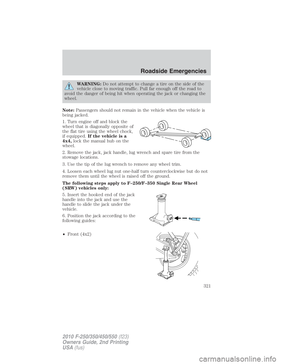
1. Turn engine off and block the
wheel that is diagonally opposite of
the flat tire using the wheel chock,
if equipped. If the vehicle is a
4x4, lock the manual hub on the
wheel.
2. Remove the jack, jack handle, lug wrench and spare tire from the
stowage locations.
3. Use the tip of the lug wrench to remove any wheel trim.
4. Loosen each wheel lug nut one-half turn counterclockwise but do not
remove them until the wheel is raised off the ground.
The following steps apply to F–250/F–350 Single Rear Wheel
(SRW) vehicles only:
5. Insert the hooked end of the jack
handle into the jack and use the
handle to slide the jack under the
vehicle.
6. Position the jack according to the
following guides:
• Front (4x2) Roadside Emergencies
321
2010 F-250/350/450/550 (f23)
Owners Guide, 2nd Printing
USA (fus)