2010 FORD F150 clock
[x] Cancel search: clockPage 94 of 419

The mirrors will automatically return to the normal state whenever the
vehicle is placed in R (Reverse) to ensure a bright clear view when
backing up.
Do not block the sensors on the front and back of the interior
rear view mirror since this may impair proper mirror
performance.
Do not clean the housing or glass of any mirror with harsh
abrasives, fuel or other petroleum-based cleaning products.
Note:If equipped with a rearview camera system, a video image will
display in the mirror or the Navigation system display (if equipped)
when the vehicle is put in R (Reverse). As you shift into any other gear
from R (Reverse), the image will remain for a few seconds and then turn
off. Refer toRearview camera systemin theDrivingchapter.
EXTERIOR MIRRORS
Power side view mirrors (if equipped)
WARNING:Do not adjust the mirror while the vehicle is in
motion.
To adjust your mirrors:
1. Rotate the control clockwise to
adjust the right mirror and rotate
the control counterclockwise to
adjust the left mirror.
2. Move the control in the direction
you wish to tilt the mirror.
3. Return to the center position to lock mirrors in place.
Memory feature (if equipped)
The power side view mirror positions are saved when doing a memory
set function and can be recalled along with the vehicle personality
features when a memory position is selected through the remote entry
transmitter, keyless entry keypad or memory switch on the driver’s seat.
Refer toMemory seats and mirrorsin theSeating and Safety
Restraintschapter.
Automatic dimming feature (if equipped)
The driver’s side view mirror has an auto-dimming function. For more
information, refer toAutomatic dimming interior rear view mirrorin
this chapter.
Driver Controls
94
2010 F-150(f12)
Owners Guide, 1st Printing
USA(fus)
Page 118 of 419
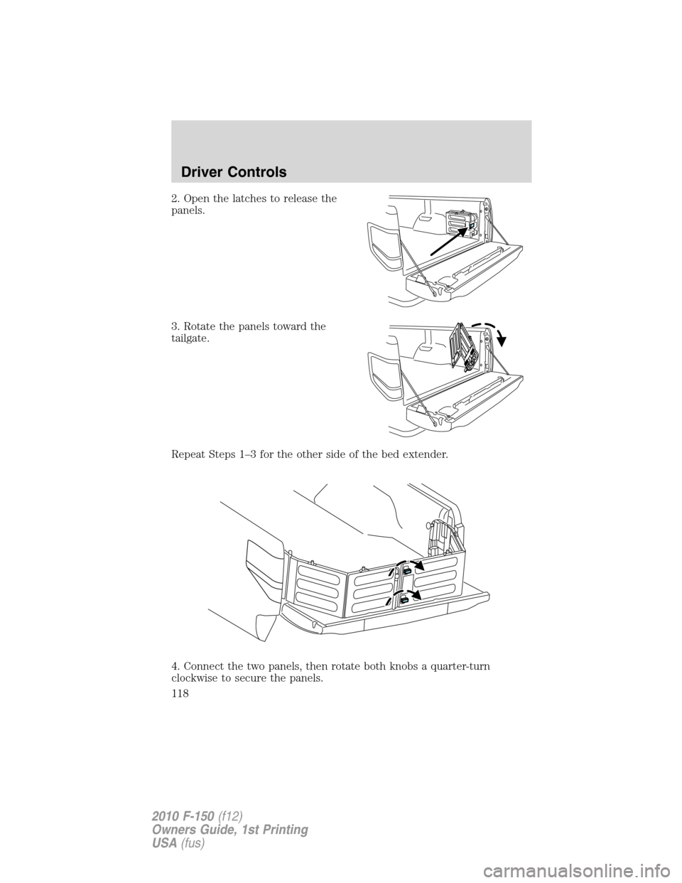
2. Open the latches to release the
panels.
3. Rotate the panels toward the
tailgate.
Repeat Steps 1–3 for the other side of the bed extender.
4. Connect the two panels, then rotate both knobs a quarter-turn
clockwise to secure the panels.
Driver Controls
118
2010 F-150(f12)
Owners Guide, 1st Printing
USA(fus)
Page 247 of 419

3. Cycle the ignition to the on
position with the engine off.
4. Turn the hazard flashers on then
off 3 times. This must be
accomplished within ten seconds.
If the reset mode has been entered successfully, the horn will sound
once, the TPMS indicator
will flash and the message center (if
equipped) will displayTRAIN LEFT FRONT TIRE. If this does not
occur, please try again starting at step 2.
If after repeated attempts to enter the reset mode, the horn does not
sound, the TPMS indicator
does not flash and the message center (if
equipped) does not displayTRAIN LEFT FRONT TIRE, seek service
from your authorized dealer.
5. Train the TPMS sensors in the tires using the following TPMS reset
sequence starting with theleft front tirein the following clockwise
order:
•Left front (Driver’s side front tire)
•Right front (Passenger’s side front tire)
•Right rear (Passenger’s side rear tire)
•Left rear (Driver’s side rear tire)
6. Remove the valve cap from the valve stem on the left front tire.
Decrease the air pressure until the horn sounds.
Note:The single horn chirp confirms that the sensor identification code
has been learned by the module for this position. If a double horn is
heard, the reset procedure was unsuccessful, and must be repeated.
7. Remove the valve cap from the valve stem on the right front tire.
Decrease the air pressure until the horn sounds.
Tires, Wheels and Loading
247
2010 F-150(f12)
Owners Guide, 1st Printing
USA(fus)
Page 332 of 419
•Wet weather driving capability
•All-Wheel driving capability (if applicable)
•Load leveling adjustment (if applicable)
When driving with the full-size dissimilar spare tire/wheel additional
caution should be given to:
•Towing a trailer
•Driving vehicles equipped with a camper body
•Driving vehicles with a load on the cargo rack
Drive cautiously when using a full-size dissimilar spare tire/wheel and
seek service as soon as possible.
Stopping and securing the vehicle
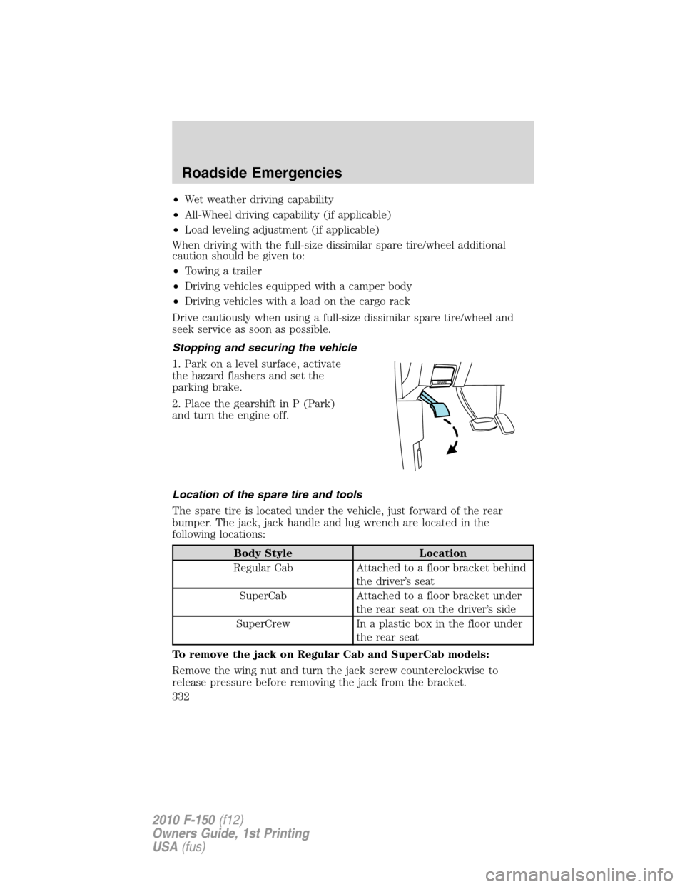
1. Park on a level surface, activate
the hazard flashers and set the
parking brake.
2. Place the gearshift in P (Park)
and turn the engine off.
Location of the spare tire and tools
The spare tire is located under the vehicle, just forward of the rear
bumper. The jack, jack handle and lug wrench are located in the
following locations:
Body Style Location
Regular Cab Attached to a floor bracket behind
the driver’s seat
SuperCab Attached to a floor bracket under
the rear seat on the driver’s side
SuperCrew In a plastic box in the floor under
the rear seat
To remove the jack on Regular Cab and SuperCab models:
Remove the wing nut and turn the jack screw counterclockwise to
release pressure before removing the jack from the bracket.
Roadside Emergencies
332
2010 F-150(f12)
Owners Guide, 1st Printing
USA(fus)
Page 333 of 419
To remove the jack on SuperCrew models:
1. Lift both rear seat cushions.
2. Remove the insert containing the Easy Fuel ™ funnel from the driver’s
side.
3. Remove the two small wing nuts on the passenger side.
4. Slide the plastic box toward the driver’s side and remove.
Removing the spare tire
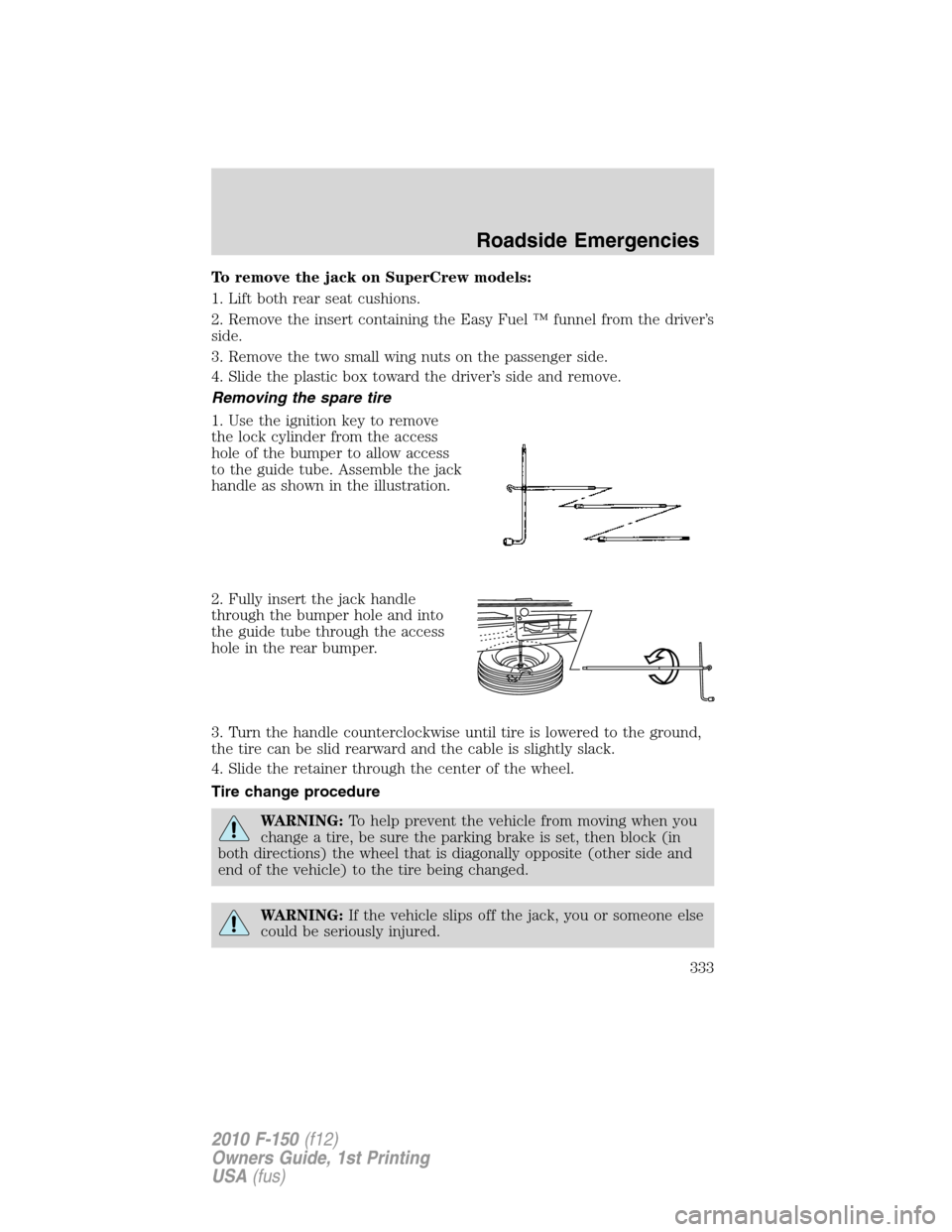
1. Use the ignition key to remove
the lock cylinder from the access
hole of the bumper to allow access
to the guide tube. Assemble the jack
handle as shown in the illustration.
2. Fully insert the jack handle
through the bumper hole and into
the guide tube through the access
hole in the rear bumper.
3. Turn the handle counterclockwise until tire is lowered to the ground,
the tire can be slid rearward and the cable is slightly slack.
4. Slide the retainer through the center of the wheel.
Tire change procedure
WARNING:To help prevent the vehicle from moving when you
change a tire, be sure the parking brake is set, then block (in
both directions) the wheel that is diagonally opposite (other side and
end of the vehicle) to the tire being changed.
WARNING:If the vehicle slips off the jack, you or someone else
could be seriously injured.
Roadside Emergencies
333
2010 F-150(f12)
Owners Guide, 1st Printing
USA(fus)
Page 334 of 419
WARNING:Do not attempt to change a tire on the side of the
vehicle close to moving traffic. Pull far enough off the road to
avoid the danger of being hit when operating the jack or changing the
wheel.
Note:Passengers should not remain in the vehicle when the vehicle is
being jacked.
Refer to the instruction sheet (located with the jack) for detailed tire
change instructions.
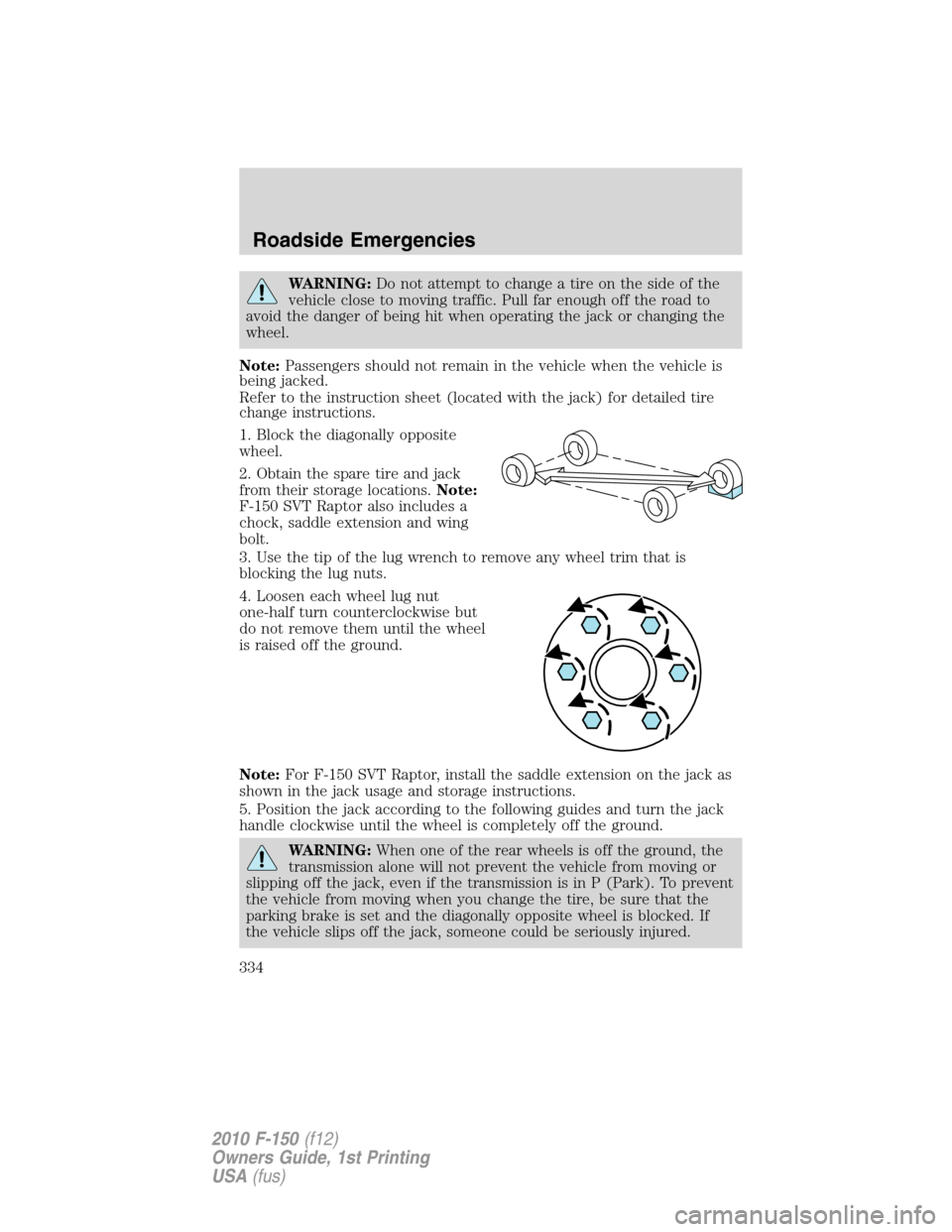
1. Block the diagonally opposite
wheel.
2. Obtain the spare tire and jack
from their storage locations.Note:
F-150 SVT Raptor also includes a
chock, saddle extension and wing
bolt.
3. Use the tip of the lug wrench to remove any wheel trim that is
blocking the lug nuts.
4. Loosen each wheel lug nut
one-half turn counterclockwise but
do not remove them until the wheel
is raised off the ground.
Note:For F-150 SVT Raptor, install the saddle extension on the jack as
shown in the jack usage and storage instructions.
5. Position the jack according to the following guides and turn the jack
handle clockwise until the wheel is completely off the ground.
WARNING:When one of the rear wheels is off the ground, the
transmission alone will not prevent the vehicle from moving or
slipping off the jack, even if the transmission is in P (Park). To prevent
the vehicle from moving when you change the tire, be sure that the
parking brake is set and the diagonally opposite wheel is blocked. If
the vehicle slips off the jack, someone could be seriously injured.
Roadside Emergencies
334
2010 F-150(f12)
Owners Guide, 1st Printing
USA(fus)
Page 336 of 419
6. Remove the lug nuts with the lug wrench.
7. Replace the flat tire with the spare tire, making sure the valve stem is
facing outward. Reinstall the lug nuts until the wheel is snug against the
hub. Do not fully tighten the lug nuts until the wheel has been lowered.
8. Lower the wheel by turning the jack handle counterclockwise.
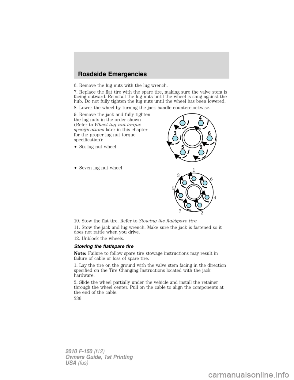
9. Remove the jack and fully tighten
the lug nuts in the order shown
(Refer toWheel lug nut torque
specificationslater in this chapter
for the proper lug nut torque
specification):
•Six lug nut wheel
•Seven lug nut wheel
10. Stow the flat tire. Refer toStowing the flat/spare tire.
11. Stow the jack and lug wrench. Make sure the jack is fastened so it
does not rattle when you drive.
12. Unblock the wheels.
Stowing the flat/spare tire
Note:Failure to follow spare tire stowage instructions may result in
failure of cable or loss of spare tire.
1. Lay the tire on the ground with the valve stem facing in the direction
specified on the Tire Changing Instructions located with the jack
hardware.
2. Slide the wheel partially under the vehicle and install the retainer
through the wheel center. Pull on the cable to align the components at
the end of the cable.
Roadside Emergencies
336
2010 F-150(f12)
Owners Guide, 1st Printing
USA(fus)
Page 337 of 419
3. Turn the jack handle clockwise until the tire is raised to its stowed
position underneath the vehicle. The effort to turn the jack handle
increases significantly and the spare tire carrier ratchets or slips when
the tire is raised to the maximum tightness. Tighten to the best of your
ability, to the point where the ratchet/slip occurs, if possible. The spare
tire carrier will not allow you to overtighten. If the spare tire carrier
ratchets or slips with little effort, take the vehicle to your authorized
dealer for assistance at your earliest convenience.
4. Check that the tire lies flat against the frame and is properly
tightened. Try to push or pull, then turn the tire to be sure it will not
move. Loosen and retighten, if necessary. Failure to properly stow the
spare tire may result in failure of the winch cable and loss of the tire.
5. Repeat this tightness check procedure when servicing the spare tire
pressure (every six months, as per yourscheduled maintenance
information),or at any time that the spare tire is disturbed through
service of other components.
6. If removed, install the spare tire lock (if equipped) into the bumper
drive tube with the spare tire lock key (if equipped) and jack handle.
WHEEL LUG NUT TORQUE SPECIFICATIONS
Retighten the lug nuts to the specified torque within 100 miles (160 km)
after any wheel disturbance (rotation, flat tire, wheel removal, etc.).
Bolt size Wheel lug nut torque*
lb.ft. N•m
M14 x 2.0 150 200
* Torque specifications are for nut and bolt threads free of dirt and
rust. Use only Ford recommended replacement fasteners.
WARNING:When a wheel is installed, always remove any
corrosion, dirt or foreign materials present on the mounting
surfaces of the wheel or the surface of the wheel hub, brake drum or
brake disc that contacts the wheel. Ensure that any fasteners that
attach the rotor to the hub are secured so they do not interfere with
the mounting surfaces of the wheel. Installing wheels without correct
metal-to-metal contact at the wheel mounting surfaces can cause the
wheel nuts to loosen and the wheel to come off while the vehicle is in
motion, resulting in loss of control.
Roadside Emergencies
337
2010 F-150(f12)
Owners Guide, 1st Printing
USA(fus)