Page 2 of 344
Locks and Security 107
Keys 107
Locks 107
Anti-theft system 118
Seating and Safety Restraints 122
Seating 122
Safety restraints 132
Airbags 147
Child restraints 162
Tires, Wheels and Loading 180
Tire information 182
Tire inflation 185
Tire Pressure Monitoring System (TPMS) 197
Vehicle loading 202
Trailer towing 210
Recreational towing 216
Driving 217
Starting 217
Brakes 222
AdvanceTrac�225
Transmission operation 233
Reverse sensing system 238
Roadside Emergencies 251
Getting roadside assistance 251
Hazard flasher control 252
Fuel pump shut-off switch 253
Fuses and relays 254
Changing tires 261
Wheel lug nut torque 269
Jump starting 270
Wrecker towing 275
Table of Contents
2
2010 07+ Explorer Sport Trac(esp)
Owners Guide(own2002), 1st Printing
USA(fus)
Page 85 of 344

To prevent the fuse from being blown, do not use the power point(s)
over the vehicle capacity of 12 VDC/180W. If the power point or cigar
lighter socket is not working, a fuse may have blown. Refer toFuses and
relaysin theRoadside Emergencieschapter for information on
checking and replacing fuses.
To have full capacity usage of your power point, the engine is required to
be running to avoid unintentional discharge of the battery. To prevent
the battery from being discharged:
•do not use the power point longer than necessary when the engine is
not running,
•do not leave battery chargers, video game adapters, computers and
other devices plugged in overnight or when the vehicle is parked for
extended periods.
Always keep the power point caps closed when not being used.
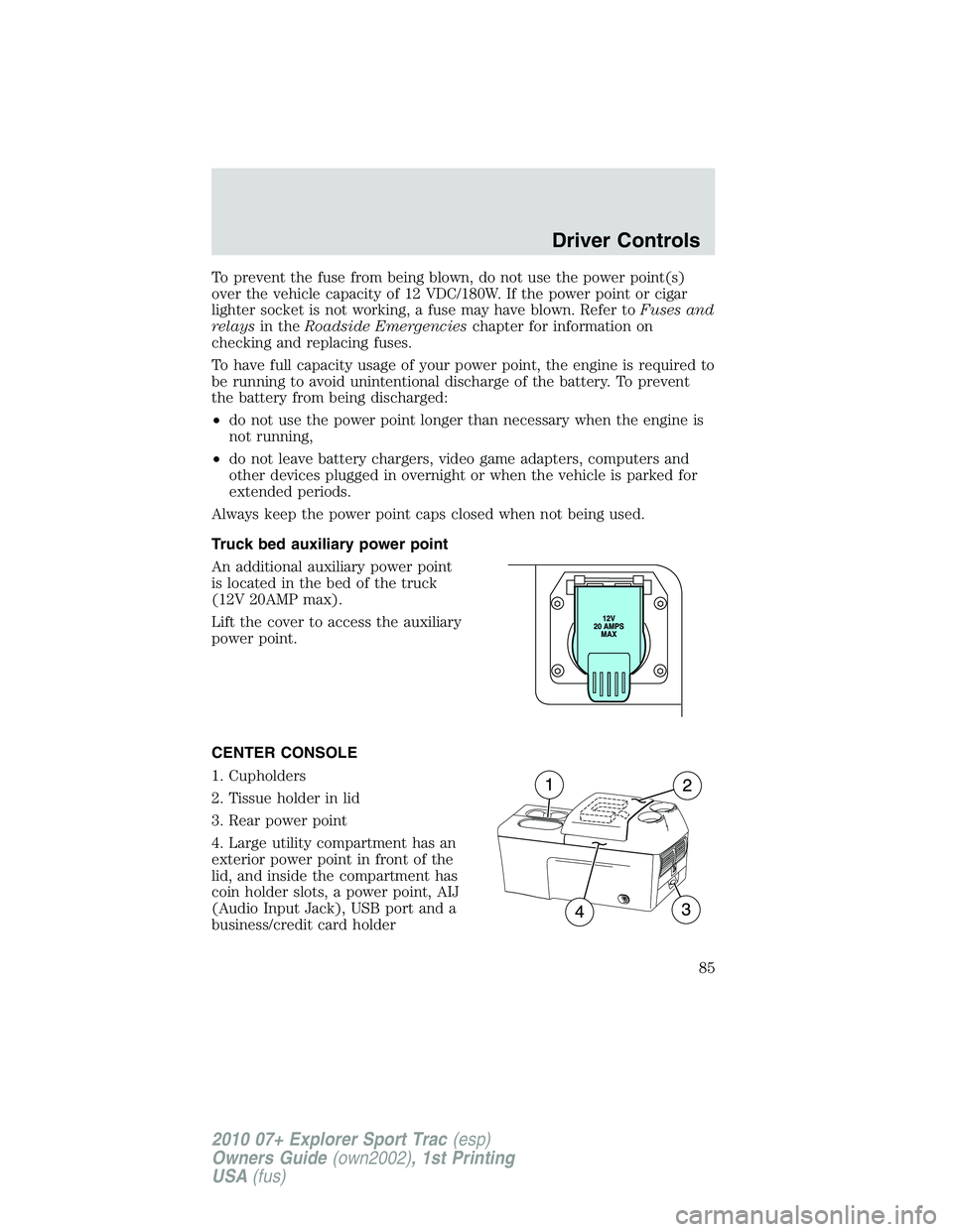
Truck bed auxiliary power point
An additional auxiliary power point
is located in the bed of the truck
(12V 20AMP max).
Lift the cover to access the auxiliary
power point.
CENTER CONSOLE
1. Cupholders
2. Tissue holder in lid
3. Rear power point
4. Large utility compartment has an
exterior power point in front of the
lid, and inside the compartment has
coin holder slots, a power point, AIJ
(Audio Input Jack), USB port and a
business/credit card holder
Driver Controls
85
2010 07+ Explorer Sport Trac(esp)
Owners Guide(own2002), 1st Printing
USA(fus)
Page 148 of 344

WARNING:Never place your arm over the airbag module as a
deploying airbag can result in serious arm fractures or other
injuries.
To properly position yourself away from the airbag:
•Move your seat to the rear as far as you can while still reaching the
pedals comfortably.
•Recline the seat slightly one or two degrees from the upright position.
WARNING:Do not put anything on or over the airbag module.
Placing objects on or over the airbag inflation area may cause
those objects to be propelled by the airbag into your face and torso
causing serious injury.
WARNING:Do not attempt to service, repair, or modify the
airbag supplemental restraint systems or its fuses. Contact your
authorized dealer as soon as possible.
WARNING:Modifications to the front end of the vehicle,
including frame, bumper, front end body structure and non-Ford
tow hooks may effect the performance of the airbag sensors increasing
the risk of injury. Do not modify the front end of the vehicle with
anything other than authorized Ford accessories for your vehicle.
WARNING:Additional equipment may affect the performance of
the airbag sensors increasing the risk of injury.
Seating and Safety Restraints
148
2010 07+ Explorer Sport Trac(esp)
Owners Guide(own2002), 1st Printing
USA(fus)
Page 156 of 344

A difficulty with the system is indicated by one or more of the following:
•The readiness light will either
flash or stay lit.
•The readiness light will not
illuminate immediately after
ignition is turned on.
•A series of five beeps will be heard. The tone pattern will repeat
periodically until the problem and/or light are repaired.
If any of these things happen, even intermittently, contact your
authorized dealer as soon as possible. Unless serviced, the system may
not function properly in the event of a collision.
Seat-mounted side airbag system
WARNING:Do not place objects or mount equipment on or
near the airbag cover on the side of the seatbacks of the front
seats or in front seat areas that may come into contact with a
deploying airbag. Failure to follow these instructions may increase the
risk of personal injury in the event of a collision.
WARNING:Do not use accessory seat covers. The use of
accessory seat covers may prevent the deployment of the side
airbags and increase the risk of injury in an accident.
WARNING:Do not lean your head on the door. The side airbag
could injure you as it deploys from the side of the seatback.
WARNING:Do not attempt to service, repair, or modify the
airbag SRS, its fuses or the seat cover on a seat containing an
airbag. Contact your authorized dealer as soon as possible.
WARNING:All occupants of the vehicle should always wear
their safety belts even when an airbag SRS is provided.
Seating and Safety Restraints
156
2010 07+ Explorer Sport Trac(esp)
Owners Guide(own2002), 1st Printing
USA(fus)
Page 158 of 344

WARNING:Several air bag system components get hot after
inflation. Do not touch them after inflation.
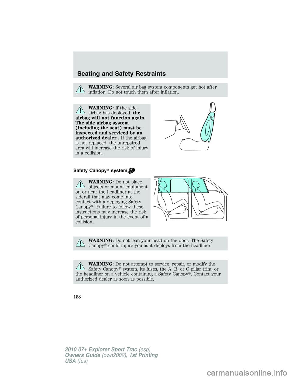
WARNING:If the side
airbag has deployed,the
airbag will not function again.
The side airbag system
(including the seat) must be
inspected and serviced by an
authorized dealer .If the airbag
is not replaced, the unrepaired
area will increase the risk of injury
in a collision.
Safety Canopy�system
WARNING:Do not place
objects or mount equipment
on or near the headliner at the
siderail that may come into
contact with a deploying Safety
Canopy�. Failure to follow these
instructions may increase the risk
of personal injury in the event of a
collision.
WARNING:Do not lean your head on the door. The Safety
Canopy�could injure you as it deploys from the headliner.
WARNING:Do not attempt to service, repair, or modify the
Safety Canopy�system, its fuses, the A, B, or C pillar trim, or
the headliner on a vehicle containing a Safety Canopy�. Contact your
authorized dealer as soon as possible.
Seating and Safety Restraints
158
2010 07+ Explorer Sport Trac(esp)
Owners Guide(own2002), 1st Printing
USA(fus)
Page 232 of 344

BRAKE-SHIFT INTERLOCK
This vehicle is equipped with a brake-shift interlock feature that prevents
the gearshift lever from being moved from P (Park) when the ignition is
in the on position unless brake pedal is pressed.
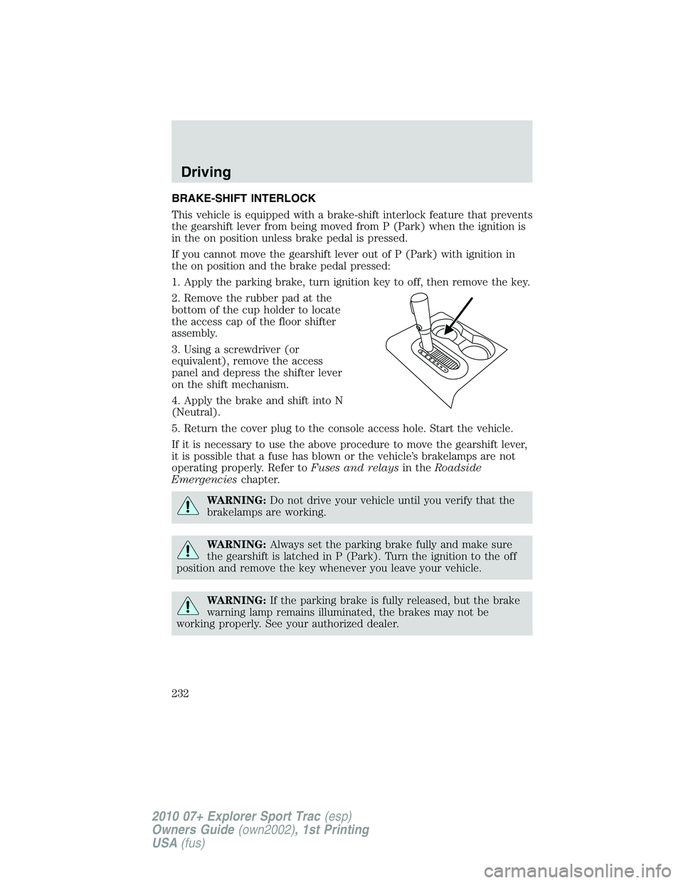
If you cannot move the gearshift lever out of P (Park) with ignition in
the on position and the brake pedal pressed:
1. Apply the parking brake, turn ignition key to off, then remove the key.
2. Remove the rubber pad at the
bottom of the cup holder to locate
the access cap of the floor shifter
assembly.
3. Using a screwdriver (or
equivalent), remove the access
panel and depress the shifter lever
on the shift mechanism.
4. Apply the brake and shift into N
(Neutral).
5. Return the cover plug to the console access hole. Start the vehicle.
If it is necessary to use the above procedure to move the gearshift lever,
it is possible that a fuse has blown or the vehicle’s brakelamps are not
operating properly. Refer toFuses and relaysin theRoadside
Emergencieschapter.
WARNING:Do not drive your vehicle until you verify that the
brakelamps are working.
WARNING:Always set the parking brake fully and make sure
the gearshift is latched in P (Park). Turn the ignition to the off
position and remove the key whenever you leave your vehicle.
WARNING:If the parking brake is fully released, but the brake
warning lamp remains illuminated, the brakes may not be
working properly. See your authorized dealer.
Driving
232
2010 07+ Explorer Sport Trac(esp)
Owners Guide(own2002), 1st Printing
USA(fus)
Page 254 of 344
FUSES AND RELAYS
Fuses
If electrical components in the
vehicle are not working, a fuse may
have blown. Blown fuses are
identified by a broken wire within
the fuse. Check the appropriate
fuses before replacing any electrical
components.
Note:Always replace a fuse with one that has the specified amperage
rating. Using a fuse with a higher amperage rating can cause severe wire
damage and could start a fire.
Standard fuse amperage rating and color
COLOR
Fuse
ratingMini fusesStandard
fusesMaxi fusesCartridge
maxi fuses
2A Grey Grey — —
3A Violet Violet — —
4A Pink Pink — —
5A Tan Tan — —
7.5A Brown Brown — —
10A Red Red — —
15A Blue Blue — —
20A Yellow Yellow Yellow Blue
25A Natural Natural — —
30A Green Green Green Pink
40A — — Orange Green
50A — — Red Red
60A — — Blue Yellow
70A — — Tan —
80A — — Natural —
15
Roadside Emergencies
254
2010 07+ Explorer Sport Trac(esp)
Owners Guide(own2002), 1st Printing
USA(fus)
Page 255 of 344
Passenger compartment fuse panel
The fuse panel is located below the
instrument panel on the driver’s
side.
To remove a fuse use the fuse puller tool provided on the fuse panel box.
The fuses are coded as follows:
Fuse/Relay
LocationFuse Amp
RatingProtected Circuits
1 20A Moon roof, Adjustable pedals
2 5A Microcontroller power
3 20A Radio, Navigation amplifier, GPS
module
4 10A On-board diagnostic (OBD II)
connector
C
B
1 4
3
2
18
7
6
51
2
1
1
1
0
91
6
1
5
1
4
1
32
0
1
9
1
8
1
72
4
2
3
2
2
2
12
8
2
7
2
6
2
5
Roadside Emergencies
255
2010 07+ Explorer Sport Trac(esp)
Owners Guide(own2002), 1st Printing
USA(fus)