Page 2 of 420
Locks and Security 161
Keys 161
Locks 162
Anti-theft system 173
Seating and Safety Restraints 183
Seating 183
Safety restraints 204
Airbags 217
Child restraints 227
Tires, Wheels and Loading 246
Tire information 248
Tire inflation 251
Tire Pressure Monitoring System (TPMS) 263
Vehicle loading 268
Trailer towing 275
Recreational towing 283
Driving 284
Starting 284
Brakes 290
AdvanceTrac�293
Air suspension 299
Transmission operation 304
Reverse sensing system 307
Rear-view camera system 310
Roadside Emergencies 324
Getting roadside assistance 324
Hazard flasher control 325
Fuel pump shut-off switch 326
Fuses and relays 327
Changing tires 335
Wheel lug nut torque 343
Jump starting 345
Wrecker towing 350
Table of Contents
2
2010 Expedition(exd)
Owners Guide(own2002), 1st Printing
USA(fus)
Page 10 of 420
These are some of the symbols you may see on your vehicle.
Vehicle Symbol Glossary
Safety Alert
See Owner’s Guide
Fasten Safety BeltAirbag - Front
Airbag - SideChild Seat Lower
Anchor
Child Seat Tether
AnchorBrake System
Anti-Lock Brake SystemParking Brake System
Brake Fluid -
Non-Petroleum BasedParking Aid System
Stability Control SystemSpeed Control
Master Lighting SwitchHazard Warning Flasher
Fog Lamps-FrontFuse Compartment
Fuel Pump ResetWindshield Wash/Wipe
Windshield
Defrost/DemistRear Window
Defrost/Demist
Introduction
10
2010 Expedition(exd)
Owners Guide(own2002), 1st Printing
USA(fus)
Page 11 of 420
Vehicle Symbol Glossary
Power Windows
Front/Rear
Power Window Lockout
Child Safety Door
Lock/UnlockInterior Luggage
Compartment Release
Panic AlarmEngine Oil
Engine CoolantEngine Coolant
Temperature
Do Not Open When HotBattery
Avoid Smoking, Flames,
or SparksBattery Acid
Explosive GasFan Warning
Power Steering FluidMaintain Correct Fluid
LevelMAX
MIN
Service Engine SoonEngine Air Filter
Passenger Compartment
Air FilterJack
Check Fuel CapLow Tire Pressure
Warning
Introduction
11
2010 Expedition(exd)
Owners Guide(own2002), 1st Printing
USA(fus)
Page 122 of 420

Replacing headlamp bulbs
1. Make sure that the headlamp control is in the off position.
2. Open the hood.
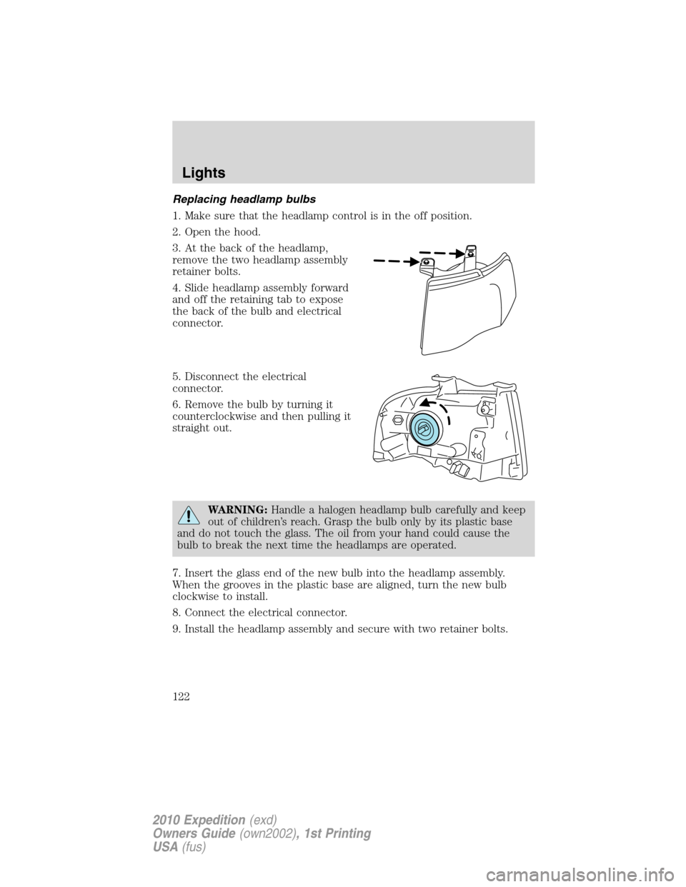
3. At the back of the headlamp,
remove the two headlamp assembly
retainer bolts.
4. Slide headlamp assembly forward
and off the retaining tab to expose
the back of the bulb and electrical
connector.
5. Disconnect the electrical
connector.
6. Remove the bulb by turning it
counterclockwise and then pulling it
straight out.
WARNING:Handle a halogen headlamp bulb carefully and keep
out of children’s reach. Grasp the bulb only by its plastic base
and do not touch the glass. The oil from your hand could cause the
bulb to break the next time the headlamps are operated.
7. Insert the glass end of the new bulb into the headlamp assembly.
When the grooves in the plastic base are aligned, turn the new bulb
clockwise to install.
8. Connect the electrical connector.
9. Install the headlamp assembly and secure with two retainer bolts.
Lights
122
2010 Expedition(exd)
Owners Guide(own2002), 1st Printing
USA(fus)
Page 155 of 420

WARNING:Keep keys out of reach of children. Do not allow
children to play near an open or moving power liftgate.
The liftgate will only operate with the vehicle in P (Park). The chime will
beep once if conditions are not correct to start an operation. These
conditions include:
•The ignition is in on and the transmission is not in P (Park)
•The battery voltage is below the minimum operating voltage
•The vehicle speed is at or above 3 mph (5 km/h)
If the liftgate reverses and starts to close after a open request, a fast
continuous chime indicates excessive load on the gate or a possible strut
failure. If any excessive load is removed and you still have a faster
chime, have the system serviced immediately by your authorized dealer.
Do not attempt to manually force the liftgate to travel faster than the
power system will permit. This will activate the obstacle detection
feature.
Note:Cycling the ignition prior to completely latching the liftgate could
result in damage to the liftgate and/or its power components. Make sure
the liftgate is fully latched before operating the vehicle.
Care should be exercised in starting the engine before the liftgate is fully
closed (latched). If the ignition is cycled during a Liftgate Power Close
cycle and the liftgate is 6-10 inches (15–24 cm) from being latched, the
liftgate may reverse to the full open position. Verify that the gate is
closed before operating or moving the vehicle, especially in an enclosure,
like a garage or a parking structure. The liftgate or it components could
be damaged in an enclosure, if the liftgate is open.
When power operating the liftgate at temperatures below 32° F (0° C),
the liftgate may stop about 5 inches (12.7 cm) from the full open
position. The liftgate can be fully opened by pushing it upward to the
maximum open position.
To open the liftgate from the
Instrument panel:
Press the button once to open the
liftgate, press it again to close.
To open the liftgate with the remote entry transmitter:
Refer toRemote entry systemin theLocks and Securitychapter.
Driver Controls
155
2010 Expedition(exd)
Owners Guide(own2002), 1st Printing
USA(fus)
Page 166 of 420

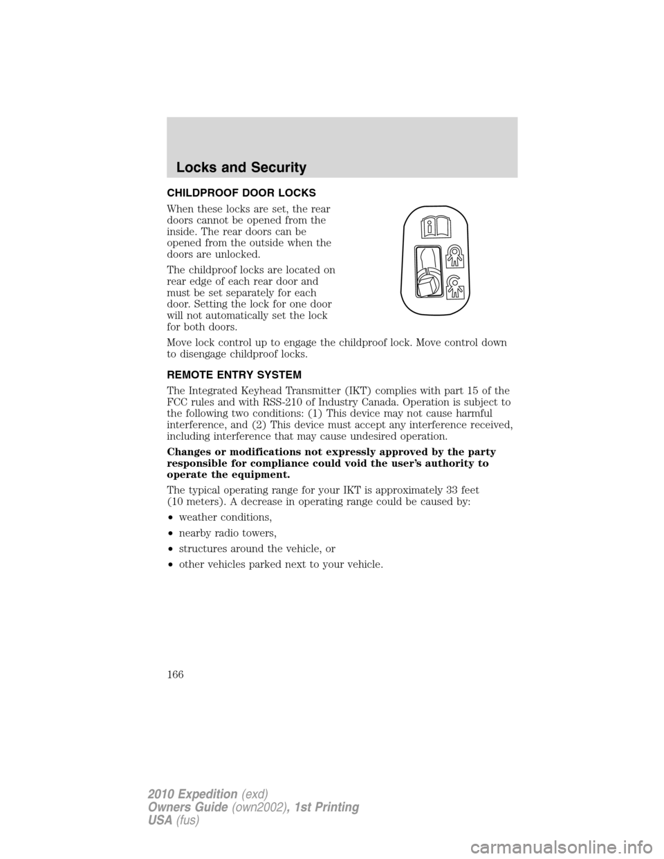
CHILDPROOF DOOR LOCKS
When these locks are set, the rear
doors cannot be opened from the
inside. The rear doors can be
opened from the outside when the
doors are unlocked.
The childproof locks are located on
rear edge of each rear door and
must be set separately for each
door. Setting the lock for one door
will not automatically set the lock
for both doors.
Move lock control up to engage the childproof lock. Move control down
to disengage childproof locks.
REMOTE ENTRY SYSTEM
The Integrated Keyhead Transmitter (IKT) complies with part 15 of the
FCC rules and with RSS-210 of Industry Canada. Operation is subject to
the following two conditions: (1) This device may not cause harmful
interference, and (2) This device must accept any interference received,
including interference that may cause undesired operation.
Changes or modifications not expressly approved by the party
responsible for compliance could void the user’s authority to
operate the equipment.
The typical operating range for your IKT is approximately 33 feet
(10 meters). A decrease in operating range could be caused by:
•weather conditions,
•nearby radio towers,
•structures around the vehicle, or
•other vehicles parked next to your vehicle.
Locks and Security
166
2010 Expedition(exd)
Owners Guide(own2002), 1st Printing
USA(fus)
Page 209 of 420

Webbing extraction sensitive mode
The webbing sensitive locking mode locks the webbing and prevents
more belt from being pulled out if the belt is pulled out too quickly. The
belt will unlock when you stop pulling on it.
Automatic locking mode
In this mode, the shoulder belt is pre-locked. The belt will still retract to
remove any slack in the shoulder belt.
The automatic locking mode is not available on the driver safety belt.
When to use the automatic locking mode
•Anytimea child safety seat (except a booster) is installed in the
vehicle. Children 12 years old and under should be properly restrained
in the rear seat whenever possible. Refer toSafety restraints for
childrenorSafety seats for childrenlater in this chapter.
How to use the automatic locking mode
1. Buckle the combination lap and
shoulder belt.
2. Grasp the shoulder portion and
pull downward until the entire belt
is pulled out.
3. Allow the belt to retract. As the belt retracts, you will hear a clicking
sound. This indicates the safety belt is now in the automatic locking
mode.
Seating and Safety Restraints
209
2010 Expedition(exd)
Owners Guide(own2002), 1st Printing
USA(fus)
Page 210 of 420

How to disengage the automatic locking mode
Unbuckle the combination lap and shoulder belt and allow it to retract
completely to disengage the automatic locking mode and return to the
vehicle sensitive (emergency) locking mode.
WARNING:After any vehicle collision, the combination lap and
shoulder belt system at all passenger seating positions must be
checked by an authorized dealer to verify that the “automatic locking
retractor” feature for child seats is still functioning properly, in addition
to other checks for proper safety belt system function.
WARNING:BELT AND RETRACTOR ASSEMBLY MUST BE
REPLACED if the safety belt assembly “automatic locking
retractor” feature or any other safety belt function is not operating
properly. In addition, all safety belts should be checked for proper
function. Failure to replace the belt and retractor assembly could
increase the risk of injury in collisions.
Safety belt pretensioner
Your vehicle is equipped with safety belt pretensioners at the driver and
right front passenger seating positions.
The safety belt pretensioner removes some slack from the safety belt
system at the start of a crash. The safety belt pretensioner uses the
same crash sensor system as the front airbags and Safety Canopy�
system. When the safety belt pretensioner deploys, the lap and shoulder
belt are tightened.
When the Safety Canopy�system and/or the front airbags are activated,
the safety belt pretensioners for the driver and right front passenger
seating positions will be activated when the respective seatbelt is
properly buckled.
WARNING:The driver and the right front passenger safety belt
system (including retractors, buckles and height adjusters) must
be replaced if the vehicle is involved in a collision that results in
deployment of front airbags or Safety Canopy�and safety belt
pretensioners.
Refer to theSafety belt maintenancesection in this chapter.
Seating and Safety Restraints
210
2010 Expedition(exd)
Owners Guide(own2002), 1st Printing
USA(fus)