Page 149 of 530
To Unfold Third Row Seats
1. Pull up on the assist strap to lift the seat out of the
storage bin and push the seat forward until the anchors
latch.
2. Pull release strap marked “1” to unlock the recliner.
3. Pulling strap “3” releases the seatback to return to its
full upright position.
4. Adjust the head restraint to the desired position.
WARNING!
In a collision, you or others in your vehicle could be
injured if seats are not properly latched to their floor
attachments. Always be sure the seats are fully
latched.
Tailgate Mode
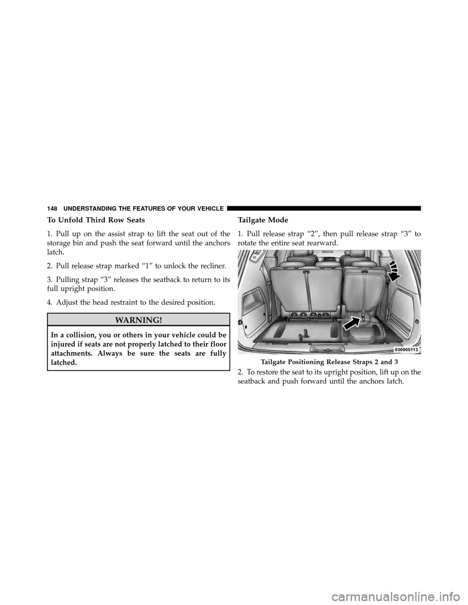
1. Pull release strap “2”, then pull release strap “3” to
rotate the entire seat rearward.
2. To restore the seat to its upright position, lift up on the
seatback and push forward until the anchors latch.
Tailgate Positioning Release Straps 2 and 3
148 UNDERSTANDING THE FEATURES OF YOUR VEHICLE
Page 320 of 530
▫Life Of Tire ........................ 361
▫ Replacement Tires .................... 361
� Snow Tires .......................... 363
� Tire Rotation Recommendations ........... 363
� Tire Pressure Monitor System (TPMS) ....... 364
▫ Base System ........................ 366
▫ Premium System – If Equipped .......... 368
� Fuel Requirements ..................... 372
▫ 3.3L And 3.8L Engine ................. 372
▫ 4.0L Engine ........................ 373
▫ Reformulated Gasoline ................ 373
▫ Gasoline/Oxygenate Blends ............. 374
▫ E85 Usage In Non-Flex Fuel Vehicles ...... 374▫
MMT In Gasoline .................... 375
▫ Materials Added To Fuel ............... 375
▫ Fuel System Cautions ................. 376
▫ Carbon Monoxide Warnings ............ 377
� Flexible Fuel (3.3L Engine Only) —
If Equipped .......................... 377
▫ E85 General Information ............... 377
▫ Ethanol Fuel (E85) ................... 379
▫ Fuel Requirements ................... 379
▫ Selection Of Engine Oil For Flexible Fuel
Vehicles E85 And Gasoline Vehicles ....... 380
▫ Starting ........................... 380
▫ Cruising Range ...................... 380
▫ Replacement Parts ................... 381
5
STARTING AND OPERATING 319
Page 364 of 530
SNOW TIRES
Some areas of the country require the use of snow tires
during Winter. Standard tires are of the all-season type
and satisfy this requirement as indicated by the M+S
designation on the tire sidewall.
If you need snow tires, select tires equivalent in size and
type to the original equipment tires. Use snow tires only
in sets of four; failure to do so may adversely affect the
safety and handling of your vehicle.
Snow tires generally have lower speed ratings than what
was originally equipped with your vehicle and should
not be operated at sustained speeds over 75 mph
(120 km/h).
TIRE ROTATION RECOMMENDATIONS
Tires on the front and rear axles of vehicles operate at
different loads and perform different steering, driving,
and braking functions. For these reasons, they wear at
unequal rates.
These effects can be reduced by timely rotation of tires.
The benefits of rotation are especially worthwhile with
aggressive tread designs such as those on All-Season type
tires. Rotation will increase tread life, help to maintain
mud, snow, and wet traction levels, and contribute to a
smooth, quiet ride.
Refer to “Maintenance Schedule” for the proper mainte-
nance intervals. More frequent rotation is permissible if
desired. The reasons for any rapid or unusual wear
should be corrected prior to rotation being performed.
5
STARTING AND OPERATING 363
Page 365 of 530
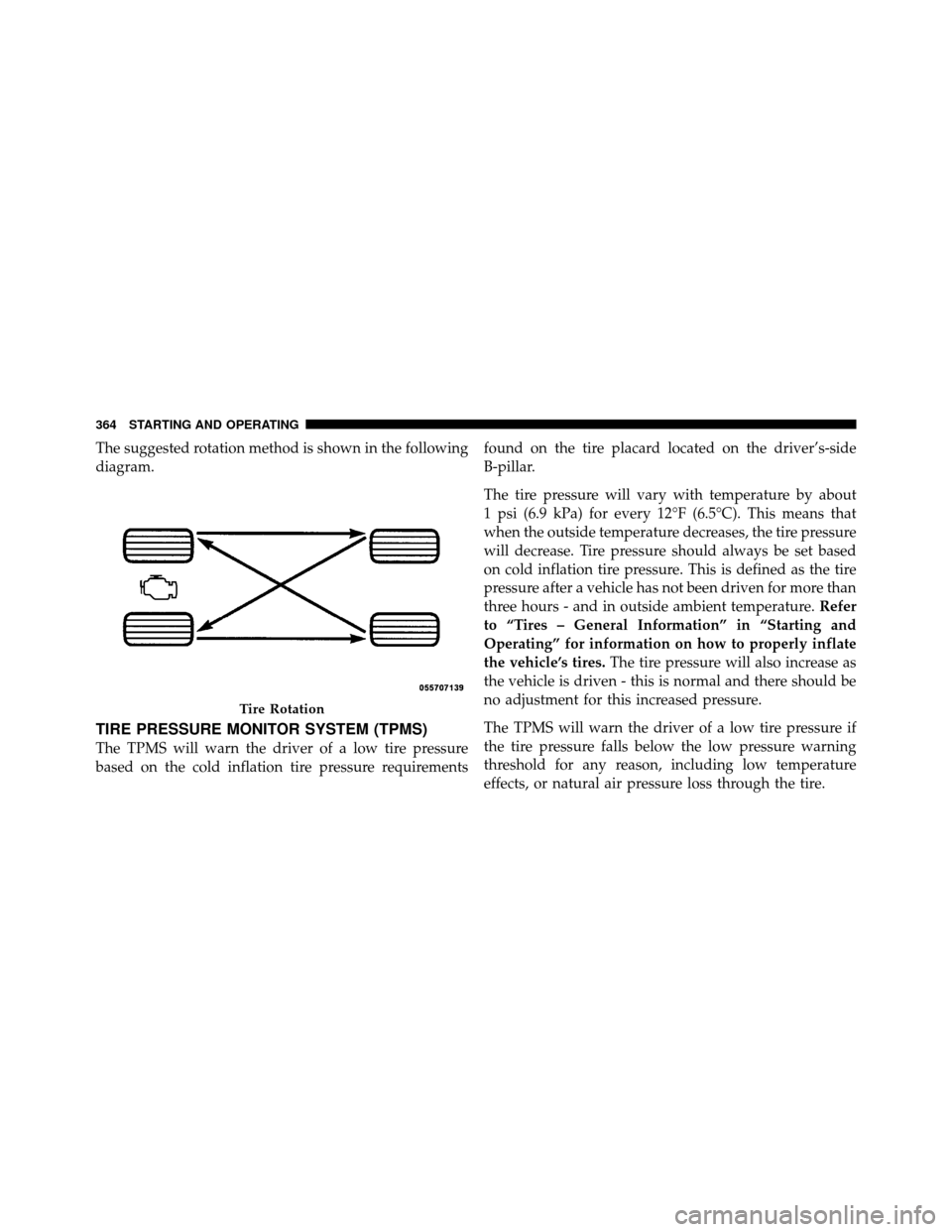
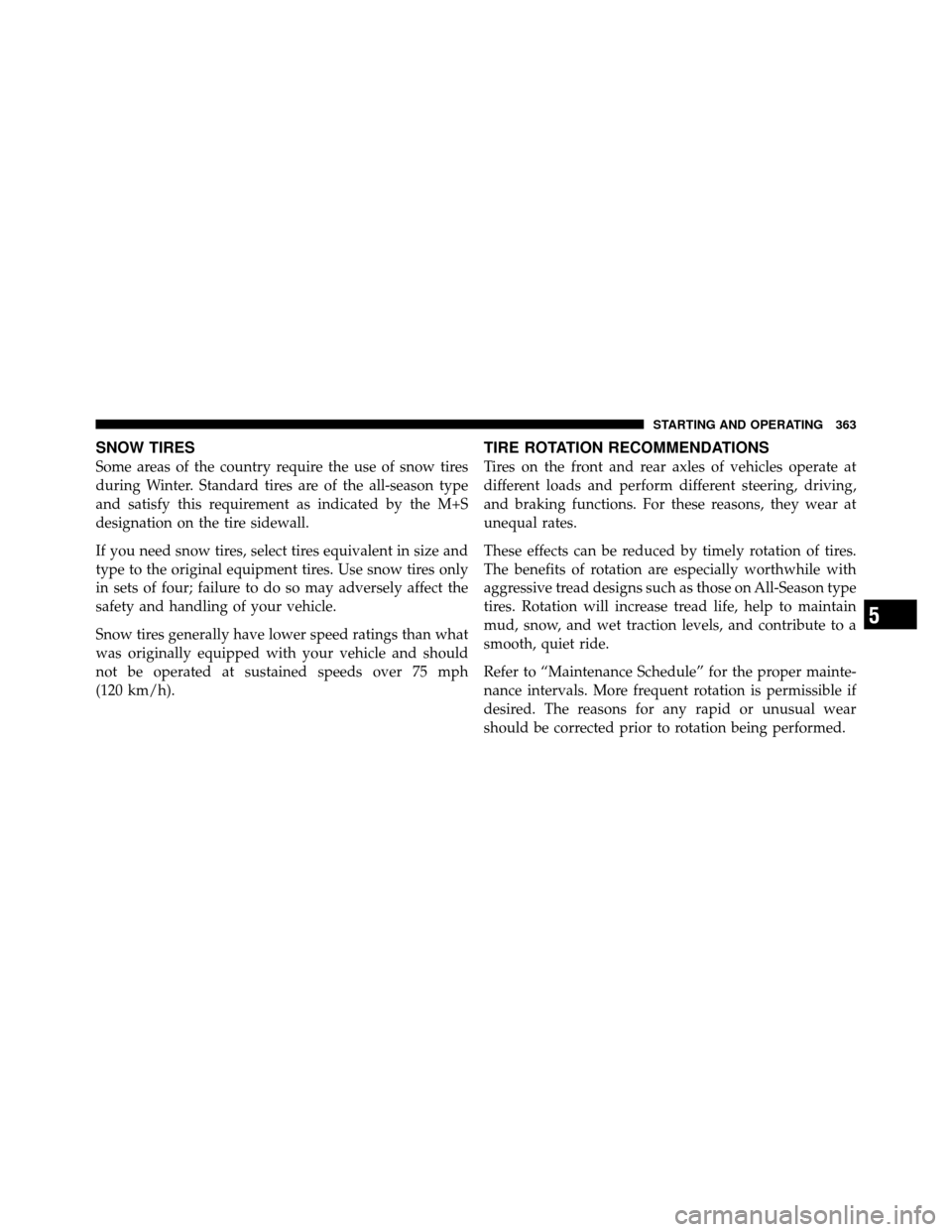
The suggested rotation method is shown in the following
diagram.
TIRE PRESSURE MONITOR SYSTEM (TPMS)
The TPMS will warn the driver of a low tire pressure
based on the cold inflation tire pressure requirementsfound on the tire placard located on the driver’s-side
B-pillar.
The tire pressure will vary with temperature by about
1 psi (6.9 kPa) for every 12°F (6.5°C). This means that
when the outside temperature decreases, the tire pressure
will decrease. Tire pressure should always be set based
on cold inflation tire pressure. This is defined as the tire
pressure after a vehicle has not been driven for more than
three hours - and in outside ambient temperature.
Refer
to “Tires – General Information” in “Starting and
Operating” for information on how to properly inflate
the vehicle’s tires. The tire pressure will also increase as
the vehicle is driven - this is normal and there should be
no adjustment for this increased pressure.
The TPMS will warn the driver of a low tire pressure if
the tire pressure falls below the low pressure warning
threshold for any reason, including low temperature
effects, or natural air pressure loss through the tire.
Tire Rotation
364 STARTING AND OPERATING
Page 413 of 530
1. Loosen (but do not remove) the wheel lug nuts by
turning them to the left one turn while the wheel is still
on the ground.
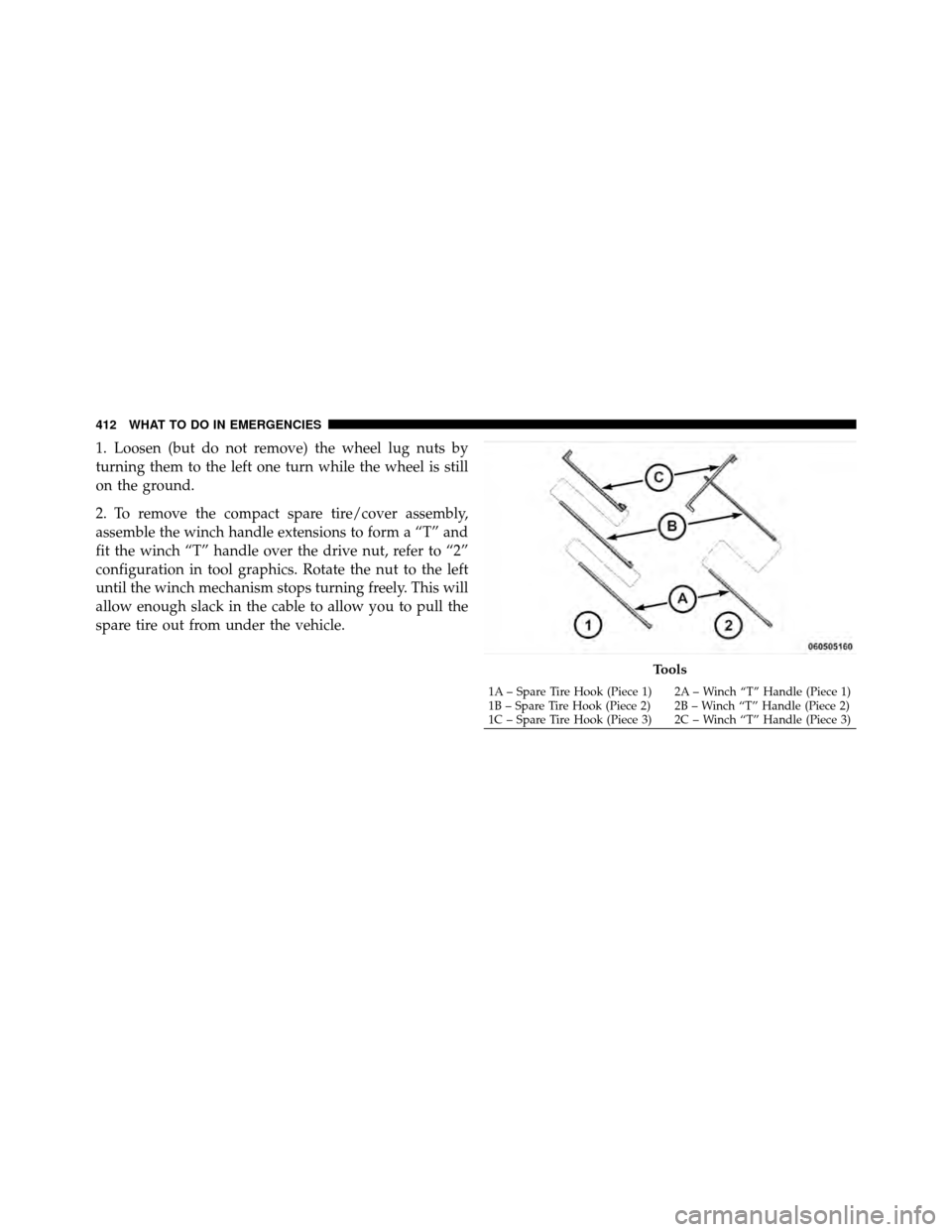
2. To remove the compact spare tire/cover assembly,
assemble the winch handle extensions to form a “T” and
fit the winch “T” handle over the drive nut, refer to “2”
configuration in tool graphics. Rotate the nut to the left
until the winch mechanism stops turning freely. This will
allow enough slack in the cable to allow you to pull the
spare tire out from under the vehicle.
Tools
1A – Spare Tire Hook (Piece 1) 2A – Winch “T” Handle (Piece 1)
1B – Spare Tire Hook (Piece 2) 2B – Winch “T” Handle (Piece 2)
1C – Spare Tire Hook (Piece 3) 2C – Winch “T” Handle (Piece 3)
412 WHAT TO DO IN EMERGENCIES
Page 419 of 530
10. Lower the vehicle by turning the jack screw to the
left.
11. Finish tightening the lug nuts. Push down on the
wrench while tightening for increased leverage. Alternate
lug nuts until each nut has been tightened twice. The
correct wheel nut tightness is 95 ft lbs (130 N·m). If in
doubt about the correct tightness, have them checked
with a torque wrench by your authorized dealer or at a
service station.
12. Lower the jack to its fully-closed position.
WARNING!
A loose tire or jack thrown forward in a collision or
hard stop could endanger the occupants of the ve-
hicle. Always stow the jack parts and the spare tire in
the places provided. Have the deflated (flat) tire
repaired or replaced immediately.13. Place the deflated (flat) tire and compact spare tire
cover assembly. in the rear cargo area.
Do not stow the
deflated tire in the spare tire location. Have the full-
sized tire repaired or replaced, as soon as possible.
14. Stow the cable and wheel spacer before driving the
vehicle. Reassemble the winch handle extensions to form
a “T” and fit the winch “T” handle over the drive nut.
Rotate the nut to the right until the winch mechanism
clicks at least three times.
15. Stow the jack, jack handle and winch handle tools.
16. Check the compact spare tire pressure as soon as
possible. Correct the tire pressure, as required.
418 WHAT TO DO IN EMERGENCIES
Page 420 of 530
Wheel Nuts
All wheel nuts should be tightened occasionally, to
eliminate the possibility of wheel studs being sheared or
the bolt holes in the wheels becoming elongated. This is
especially important during the first few hundred miles
of operation, and after each time a tire is changed, to
allow the wheel nuts to become properly set. All nuts
should first be firmly seated against the wheel. The nuts
should then be tightened to recommended torque.
Tighten the nuts to final torque in increments. Progress
around the bolt circle, tightening the nut opposite to the
nut just previously tightened until final torque is
achieved. Recommended torque is 95 ft lbs (130 N·m).
Secure The Spare Tire
1. Assemble the winch handle extensions to form a “T”
and fit the winch “T” handle over the drive nut. Rotate
the nut to the left until the winch mechanism stopsturning freely. This will allow enough slack in the cable to
allow you to pull the wheel spacer out from under the
vehicle.
WARNING!
A loose compact spare tire/cover assembly, thrown
forward in a collision or hard stop could endanger
the occupants of the vehicle. Always stow the com-
pact spare tire with the cover assembly in the place
provided.
CAUTION!
The winch mechanism is designed for use with the
winch “T” handle only. Use of an air wrench or other
power tools is not recommended and can damage the
winch.
6
WHAT TO DO IN EMERGENCIES 419
Page 421 of 530
2. Assemble the winch handle extensions to form the
spare tire hook, and pull the wheel spacer from under the
vehicle.
3. Turn the compact spare tire so that the valve stem is
down, and place the tire into the spare tire/cover assem-
bly. Slide the wheel spacer through the center of the
wheel and spare tire/cover assembly, so that the two
retainer tabs snap out and engage the spare tire cover on
the opposite side.
CAUTION!
The compact spare tire/cover assembly must be used
when the compact spare tire is stored. Failure to use
this cover could drastically reduce the life of the
compact spare tire.
WARNING!
Verify that both retainer tabs of the wheel spacer
have been properly extended through the center of
the wheel and spare tire/cover assembly. Failure to
properly engage both retainer tabs could result in
loss of the spare tire and cover assembly, which will
cause vehicle damage and may cause loss of vehicle
control.
4. Using the winch “T” handle, rotate the drive nut to the
right until the compact spare tire/cover assembly is
drawn into place against the underside of the vehicle.
5. Continue to rotate the nut to the right until you hear
the winch mechanism click three times. It cannot be
overtightened. Check under the vehicle to ensure the
compact spare tire/cover assembly is positioned cor-
rectly against the underside of the vehicle.
420 WHAT TO DO IN EMERGENCIES