Page 333 of 450
HAZARD WARNING FLASHER
The Hazard Warning flasher switch is located on the top
of the steering column, just behind the steering wheel.Press the switch to turn on the Hazard Warning
flasher. When the switch is activated, all directional
turn signals will flash on and off to warn oncoming
traffic of an emergency. Press the switch a second time to
turn off the Hazard Warning flasher.
This is an emergency warning system and should not be
used when the vehicle is in motion. Use it when your
vehicle is disabled and is creating a safety hazard for
other motorists.
If it is necessary to leave the vehicle to go for service, the
Hazard Warning flasher will continue to operate with the
ignition key removed and the vehicle locked.
NOTE: With extended use, the Hazard Warning flasher
may wear down your battery.
Hazard Warning Flasher Switch
332 WHAT TO DO IN EMERGENCIES
Page 336 of 450

WARNING!
The jack is designed as a tool for changing tires only.
The jack should not be used to lift the vehicle for
service purposes, unless suitable supports are placed
under the vehicle as a safety measure. The vehicle
should be jacked on a firm level surface only. Avoid
icy or slippery areas.
Removing The Spare Tire
Remove the spare tire before attempting to jack the truck.
Attach the wheel wrench to the jack extension tube. Insert
the tube through the access hole in the rear bumper and
into the winch mechanism tube. Rotate the wheel wrench
handle counterclockwise until the spare tire is on the
ground with enough cable slack to allow you to pull it
out from under the vehicle. When the spare is clear, tilt
the retainer at the end of the cable and pull it through the
center of the wheel.Steps for Removing the Spare Tire
•Remove the jack from the stowage compartment using
the supplied finger-assist tool.
•Remove the finger-assist tool from jack and set aside
until jack is stowed.
•Assemble the jack tools.
•Locate the tire carrier access hole on the rear bumper.
•Place assembled jack tool extension rod into the access
hole in the direction of the arrow on the bumper trim.
•Rotate the tool counterclockwise to release and lower
the spare tire to the ground so that it can be pulled
from under the vehicle.
6
WHAT TO DO IN EMERGENCIES 335
Page 338 of 450
It is recommended that you stow the flat or spare to
avoid tangling the loose cable.
NOTE:The winch mechanism is designed for use with
the jack extension tube only. Use of an air wrench or other
power tools is not recommended and can damage the
winch.Tire Changing Procedure
WARNING!
Getting under a jacked-up vehicle is dangerous. The
vehicle could slip off the jack and fall on you. You
could be crushed. Never get any part of your body
under a vehicle that is on a jack. Never start or run
the engine while the vehicle is on a jack. If you need
to get under a raised vehicle, take it to a service center
where it can be raised on a lift.
Do not raise this vehicle using a bumper jack. The scissor
jack is designed as a tool for changing tires on this vehicle
only. It is not recommended that the jack be used for
service purposes or to lift more than one wheel at a time.
Spare Tire Stowage Location
6
WHAT TO DO IN EMERGENCIES 337
Page 342 of 450

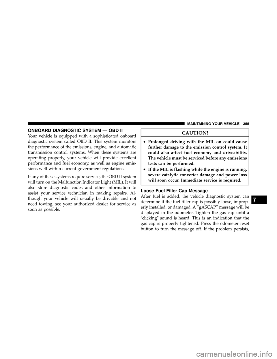
NOTE: Before raising the wheel off the ground, make
sure that the jack will not damage surrounding truck
parts and adjust the jack position as required.
5. By rotating the wheel wrench clockwise, raise the
vehicle until the wheel just clears the surface.
WARNING!
Raising the vehicle higher than necessary can make
the vehicle unstable and cause an accident. It could
slip off the jack and hurt someone near it. Raise the
vehicle only enough to remove the tire.
6. Remove the wheel nuts and pull the wheel off. Install
the spare wheel and wheel nuts with the cone shaped end
of the nuts toward the wheel. Lightly tighten the nuts. To
avoid risk of forcing the vehicle off the jack, do not fully
tighten the nuts until the vehicle has been lowered.
7. Using the wheel wrench, finish tightening the nuts in
a crisscross pattern. The correct nut tightness is 120 to
160 ft lbs (163 to 217 N·m). If in doubt about the correct
tightness, have them checked with a torque wrench by
your authorized dealer or at a service station.
Right Rear Jacking Location6
WHAT TO DO IN EMERGENCIES 341
Page 352 of 450
MAINTAINING YOUR VEHICLE
CONTENTS
�Engine Compartment — 3.7L ............. 353
� Engine Compartment — 4.7L ............. 354
� Onboard Diagnostic System — OBD II ...... 355
▫ Loose Fuel Filler Cap Message ........... 355
� Emissions Inspection And Maintenance
Programs ............................ 356
� Replacement Parts ..................... 357
� Dealer Service ........................ 358
� Maintenance Procedures ................. 358 ▫
Engine Oil ......................... 359
▫ Engine Oil Filter ..................... 361
▫ Engine Air Cleaner Filter ............... 362
▫ Maintenance-Free Battery .............. 362
▫ Air Conditioner Maintenance ............ 363
▫ Body Lubrication .................... 364
▫ Windshield Wiper Blades ............... 365
▫ Adding Washer Fluid ................. 365
7
Page 356 of 450

ONBOARD DIAGNOSTIC SYSTEM — OBD II
Your vehicle is equipped with a sophisticated onboard
diagnostic system called OBD II. This system monitors
the performance of the emissions, engine, and automatic
transmission control systems. When these systems are
operating properly, your vehicle will provide excellent
performance and fuel economy, as well as engine emis-
sions well within current government regulations.
If any of these systems require service, the OBD II system
will turn on the Malfunction Indicator Light (MIL). It will
also store diagnostic codes and other information to
assist your service technician in making repairs. Al-
though your vehicle will usually be drivable and not
need towing, see your authorized dealer for service as
soon as possible.CAUTION!
•Prolonged driving with the MIL on could cause
further damage to the emission control system. It
could also affect fuel economy and driveability.
The vehicle must be serviced before any emissions
tests can be performed.
•If the MIL is flashing while the engine is running,
severe catalytic converter damage and power loss
will soon occur. Immediate service is required.
Loose Fuel Filler Cap Message
After fuel is added, the vehicle diagnostic system can
determine if the fuel filler cap is possibly loose, improp-
erly installed, or damaged. A “gASCAP” message will be
displayed in the odometer. Tighten the gas cap until a
�clicking�sound is heard. This is an indication that the
gas cap is properly tightened. Press the odometer reset
button to turn the message off. If the problem persists,
7
MAINTAINING YOUR VEHICLE 355
Page 357 of 450

the message will appear the next time the vehicle is
started. This might indicate a damaged cap. If the prob-
lem is detected twice in a row, the system will turn on the
MIL. Resolving the problem will turn the MIL off.
EMISSIONS INSPECTION AND MAINTENANCE
PROGRAMS
In some localities, it may be a legal requirement to pass
an inspection of your vehicle’s emissions control system.
Failure to pass could prevent vehicle registration.For states that require an Inspection and Mainte-
nance (I/M), this check verifies the “Malfunction
Indicator Light (MIL)” is functioning and is not
on when the engine is running, and that the OBD II
system is ready for testing.
Normally, the OBD II system will be ready. The OBD II
system may notbe ready if your vehicle was recently serviced, recently had a dead battery or a battery replace-
ment. If the OBD II system should be determined not
ready for the I/M test, your vehicle may fail the test.
Your vehicle has a simple ignition key-actuated test,
which you can use prior to going to the test station. To
check if your vehicle’s OBD II system is ready, you must
do the following:
1. Turn the ignition switch to the ON position, but do not
crank or start the engine.
2. If you crank or start the engine, you will have to start
this test over.
3. As soon as you turn the ignition switch to the ON
position, you will see the MIL symbol come on as part of
a normal bulb check.
356 MAINTAINING YOUR VEHICLE
Page 358 of 450

4. Approximately 15 seconds later, one of two things will
happen:a. The MIL will flash for about 10 seconds and then
return to being fully illuminated until you turn OFF
the ignition or start the engine. This means that your
vehicle’s OBD II system is not readyand you should
not proceed to the I/M station.
b. The MIL will not flash at all and will remain fully
illuminated until you turn OFF the ignition or start the
engine. This means that your vehicle’s OBD II system
is ready and you can proceed to the I/M station.
If your OBD II system is not ready,you should see your
authorized dealer or repair facility. If your vehicle was
recently serviced or had a battery failure or replacement,
you may need to do nothing more than drive your vehicle as you normally would in order for your OBD II
system to update. A recheck with the above test routine
may then indicate that the system is now ready.
Regardless of whether your vehicle’s OBD II system is
ready or not, if the MIL is illuminated during normal
vehicle operation you should have your vehicle serviced
before going to the I/M station. The I/M station can fail
your vehicle because the MIL is on with the engine running.
REPLACEMENT PARTS
Use of genuine MOPAR�
parts for normal/scheduled
maintenance and repairs is highly recommended to ensure
the designed performance. Damage or failures caused by
the use of non-MOPAR� parts for maintenance and repairs
will not be covered by the manufacturer’s warranty.
7
MAINTAINING YOUR VEHICLE 357