Page 168 of 450
4. Snap the tailgate support cable between the cable
guide and the tailgate bumper. Do this on both sides of
the tailgate.
To return the tailgate to the full-open position:
1. Lift up on the tailgate.2. Remove both cables from between the cable guides
and the tailgate bumpers, and lower the tailgate.
CAUTION!
•Care should always be exercised when operating a
vehicle with cargo. Vehicle speeds may need to be
reduced. Severe turns or rough roads may cause
shifting or bouncing of the cargo that may result in
vehicle damage.
•Ensure the load is securely tied down and is
properly identified according to local laws if it
extends beyond the tail lights.
•Loading should not exceed 400 lbs (181 kg) of
material suspended above the wheelhouse and
partially open tailgate or vehicle damage may
result.
Tailgate Guide
3
UNDERSTANDING THE FEATURES OF YOUR VEHICLE 167
Page 186 of 450

maintain correct tire pressure, even if under-inflation has
not reached the level to trigger illumination of the TPMS
low tire pressure telltale.
Your vehicle has also been equipped with a TPMS
malfunction indicator to indicate when the system is not
operating properly. The TPMS malfunction indicator is
combined with the low tire pressure telltale. When the
system detects a malfunction, the telltale will flash for
approximately one minute and then remain continuously
illuminated. This sequence will continue upon subse-
quent vehicle start-ups as long as the malfunction exists.
When the malfunction indicator is illuminated, the sys-
tem may not be able to detect or signal low tire pressure
as intended. TPMS malfunctions may occur for a variety
of reasons, including the installation of replacement or
alternate tires or wheels on the vehicle that prevent the
TPMS from functioning properly. Always check the
TPMS malfunction telltale after replacing one or moretires or wheels on your vehicle, to ensure that the
replacement or alternate tires and wheels allow the TPMS
to continue to function properly.
CAUTION!
The TPMS has been optimized for the original
equipment tires and wheels. TPMS pressures and
warning have been established for the tire size
equipped on your vehicle. Undesirable system opera-
tion or sensor damage may result when using re-
placement equipment that is not of the same size,
type, and/or style. Aftermarket wheels can cause
sensor damage. Do not use tire sealant from a can, or
balance beads if your vehicle is equipped with a
TPMS, as damage to the sensors may result.
4
UNDERSTANDING YOUR INSTRUMENT PANEL 185
Page 187 of 450

23. Airbag Warning LightThe airbag warning light will illuminate and
remain lit for six to eight seconds when the
ignition is first turned ON. If the light does not
illuminate when the ignition is first turned ON,
or the light stays on or comes on while driving, have the
airbag system checked by an authorized dealer. Refer to
“Occupant Restraints” in “Things To Know Before Start-
ing Your Vehicle” for further information.
24. 4WD Indicator This light indicates the vehicle is in four-wheel
drive and 4LOCK. 4WD allows all four wheels
to receive torque from the engine simulta-
neously.
25. SVC (Service) 4WD Indicator
The SVC 4WD illuminates when the ignition key is
turned to the ON position and will stay on for two seconds. If the light stays on or illuminates during
driving, it means that the 4WD system is not functioning
properly and that service is required.
26. Cruise Indicator
The cruise indicator illuminates when the electronic
speed control system is turned on.
27. Cargo Lamp
The Cargo Lamp indicator will illuminate
when the Cargo Lamp is activated by pressing
the CARGO button, located on the headlight
switch.
28. TOW/HAUL
The TOW/HAUL button is located at the end of the gear
shift lever. This light will illuminate when the TOW/
HAUL button has been selected.
186 UNDERSTANDING YOUR INSTRUMENT PANEL
Page 188 of 450

29. 4WD LOW Indicator
This light alerts the driver that the vehicle is in
the four-wheel drive LOW mode. The front and
rear driveshafts are mechanically locked to-
gether forcing the front and rear wheels to rotate
at the same speed. Low range provides a greater gear
reduction ratio to provide increased torque at the wheels.
30. Odometer/Trip Odometer Button
Press the ODOMETER/TRIP ODOMETER button to
toggle between the odometer and the trip odometer
display. Holding the button in, resets the trip odometer
reading.
ELECTRONIC DIGITAL CLOCK
The clock and radio each use the display panel built into
the radio. A digital readout shows the frequency and/or
time in hours and minutes (depending on your radio
model), whenever the ignition switch is in the ON or
ACC position. When the ignition switch is in the OFF position, or when
the radio frequency is being displayed, timekeeping is
accurately maintained.
On the AM/FM/CD (6-disc) radio, the time button
alternates the location of the time and frequency on the
display. On the AM/FM/CD (single-disc) radio, only one
of the two, time or frequency, is displayed.
Clock Setting Procedure
1. Press and hold the TIME button until the hours blink.
2. Adjust the hours by turning the TUNE/AUDIO con-
trol knob.
3. After the hours are adjusted, push the TUNE/AUDIO
control knob to set the minutes.
4. Adjust the minutes by turning the TUNE/AUDIO
control knob.
5. To exit, press any button/knob, or wait approximately
five seconds.
4
UNDERSTANDING YOUR INSTRUMENT PANEL 187
Page 236 of 450

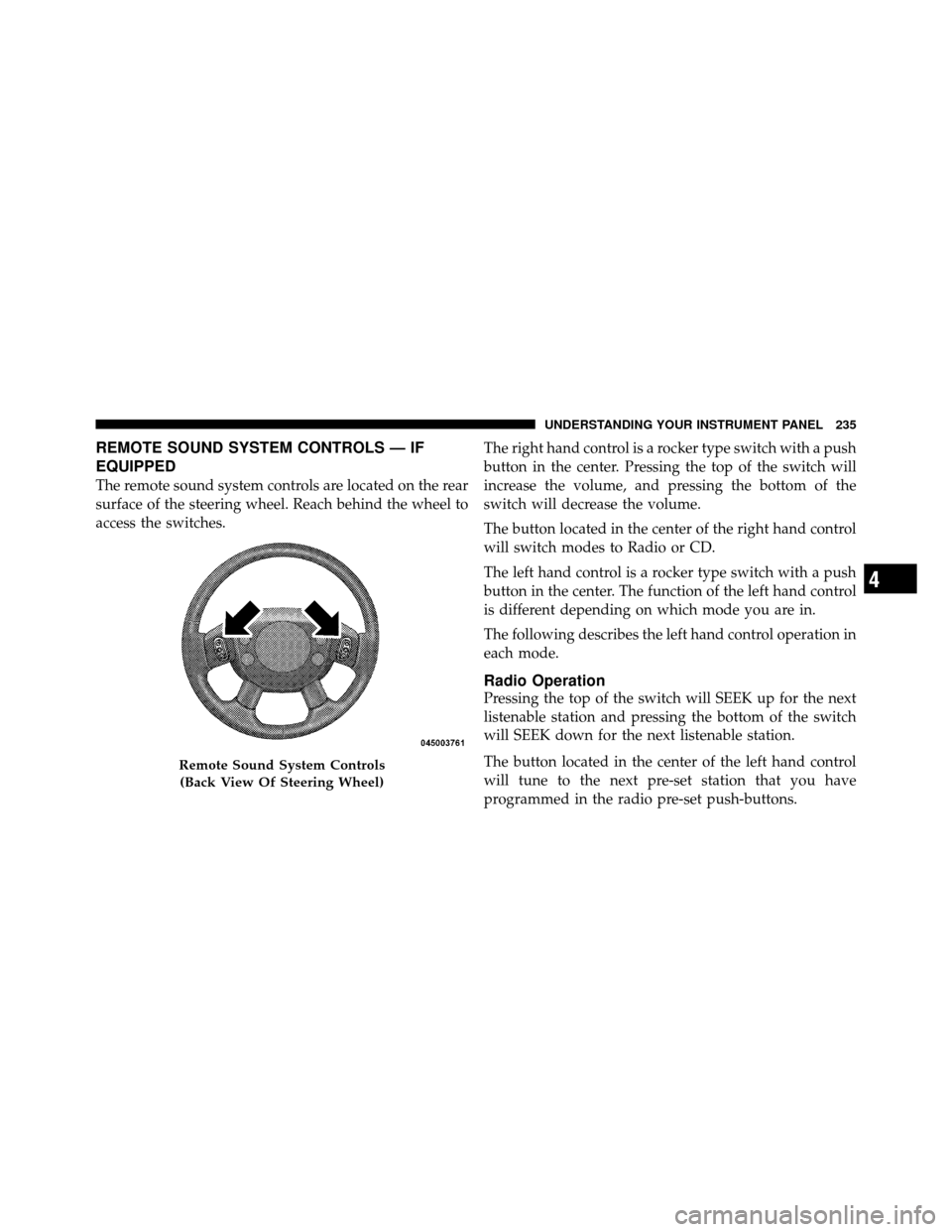
REMOTE SOUND SYSTEM CONTROLS — IF
EQUIPPED
The remote sound system controls are located on the rear
surface of the steering wheel. Reach behind the wheel to
access the switches.The right hand control is a rocker type switch with a push
button in the center. Pressing the top of the switch will
increase the volume, and pressing the bottom of the
switch will decrease the volume.
The button located in the center of the right hand control
will switch modes to Radio or CD.
The left hand control is a rocker type switch with a push
button in the center. The function of the left hand control
is different depending on which mode you are in.
The following describes the left hand control operation in
each mode.
Radio Operation
Pressing the top of the switch will SEEK up for the next
listenable station and pressing the bottom of the switch
will SEEK down for the next listenable station.
The button located in the center of the left hand control
will tune to the next pre-set station that you have
programmed in the radio pre-set push-buttons.
Remote Sound System Controls
(Back View Of Steering Wheel)
4
UNDERSTANDING YOUR INSTRUMENT PANEL 235
Page 246 of 450
STARTING AND OPERATING
CONTENTS
�Starting Procedures .................... 249
▫ Automatic Transmission ............... 249
▫ Normal Starting ..................... 249
▫ Extreme Cold Weather
(Below –20°F Or –29°C) ................ 250
▫ If Engine Fails To Start ................ 250
▫ After Starting ....................... 251
� Engine Block Heater — If Equipped ........ 251
� Automatic Transmission ................. 252 ▫
Key Ignition Park Interlock ............. 252
▫ Brake/Transmission Interlock System ...... 253
▫ Automatic Transmission ............... 253
▫ Gear Ranges ........................ 253
� Four-Wheel Drive Operation — If Equipped . . 258
▫ NV233/243 GII Transfer Case Operating
Information/Precautions ............... 258
▫ Shifting Procedure – NV233/243 Transfer
Case ............................. 262
5
Page 247 of 450

�Limited-Slip Rear Axle Differential —
If Equipped .......................... 264
� Driving On Slippery Surfaces ............. 264
� Driving Through Water ................. 265
▫ Flowing/Rising Water ................. 265
▫ Shallow Standing Water ............... 265
� Power Steering ....................... 267
▫ Power Steering Fluid Check ............. 268
� Parking Brake ........................ 269
� Brake System ........................ 270
▫ Rear-Wheel Anti-Lock Brake System (ABS) . . 270
▫ Four-Wheel Anti-Lock Brake System (ABS) —
If Equipped ........................ 271
� Tire Safety Information ................. 273 ▫
Tire Markings ....................... 273
▫ Tire Identification Number (TIN) ......... 277
▫ Tire Terminology And Definitions ......... 278
▫ Tire Loading And Tire Pressure .......... 279
� Tires — General Information ............. 283
▫ Tire Pressure ....................... 283
▫ Tire Inflation Pressures ................ 284
▫ Tire Pressures For High Speed Operation . . . 285
▫ Radial Ply Tires ..................... 286
▫ Tire Spinning ....................... 286
▫ Tread Wear Indicators ................. 287
▫ Life Of Tire ........................ 288
▫ Replacement Tires .................... 288
246 STARTING AND OPERATING
Page 249 of 450
▫Loose Fuel Filler Cap Message ........... 308
� Vehicle Loading ...................... 309
▫ Certification Label ................... 309
▫ Curb Weight ........................ 310
▫ Loading ........................... 310
� Trailer Towing ........................ 311
▫ Common Towing Definitions ............ 312
▫ Trailer Hitch Classification .............. 316
▫ Trailer Towing Weights
(Maximum Trailer Weight Ratings) ........ 317▫
Trailer And Tongue Weight ............. 317
▫ Towing Requirements ................. 318
▫ Towing Tips ........................ 323
� Snowplow .......................... 324
� Recreational Towing
(Behind Motorhome, Etc.) ................ 325
▫ Two-Wheel Drive Models .............. 325
▫ Four-Wheel Drive Models .............. 325
248 STARTING AND OPERATING