Page 235 of 538
vehicle is experiencing a problem with the charging
system. Obtain SERVICE IMMEDIATELY. See an autho-
rized dealer.
If jump starting is required, refer to “Jump Starting
Procedures” in “What To Do In Emergencies”.
5. Tire Pressure Monitoring Telltale Light — If
EquippedEach tire, including the spare (if provided),
should be checked monthly, when cold and
inflated to the inflation pressure recommended
by the vehicle manufacturer on the vehicle
placard or tire inflation pressure label. (If your vehicle
has tires of a different size than the size indicated on the
vehicle placard or tire inflation pressure label, you should
determine the proper tire inflation pressure for those
tires.)
As an added safety feature, your vehicle has been
equipped with a Tire Pressure Monitoring System (TPMS) that illuminates a low tire pressure telltale when
one or more of your tires is significantly under-inflated.
Accordingly, when the low tire pressure telltale illumi-
nates, you should stop and check your tires as soon as
possible, and inflate them to the proper pressure. Driving
on a significantly under-inflated tire causes the tire to
overheat and can lead to tire failure. Under-inflation also
reduces fuel efficiency and tire tread life, and may affect
the vehicle’s handling and stopping ability.
Please note that the TPMS is not a substitute for proper
tire maintenance, and it is the driver ’s responsibility to
maintain correct tire pressure, even if under-inflation has
not reached the level to trigger illumination of the TPMS
low tire pressure telltale.
Your vehicle has also been equipped with a TPMS
malfunction indicator to indicate when the system is not
operating properly. The TPMS malfunction indicator is
combined with the low tire pressure telltale. When the
234 UNDERSTANDING YOUR INSTRUMENT PANEL
Page 325 of 538
�Driving Through Water ................. 339
▫ Flowing/Rising Water ................. 339
▫ Shallow Standing Water ............... 339
� Power Steering ....................... 341
▫ Power Steering Fluid Check ............. 342
� Parking Brake ........................ 343
� Anti-Lock Brake System (ABS) ............ 345
▫ Anti-Lock Brake Warning Light .......... 347
� Electronic Brake Control System ........... 347
▫ Traction Control System (TCS) ........... 347
▫ Brake Assist System (BAS) .............. 349
▫ Electronic Stability Program (ESP) ........ 350
▫ ESP/BAS Warning Light ............... 351 �
Tire Safety Information ................. 352
▫ Tire Markings ....................... 352
▫ Tire Identification Number (TIN) ......... 355
▫ Tire Terminology And Definitions ......... 356
▫ Tire Loading And Tire Pressure .......... 357
� Tires — General Information ............. 361
▫ Tire Pressure ....................... 361
▫ Tire Inflation Pressures ................ 362
▫ Tire Pressures For High-Speed Operation . . . 363
▫ Radial-Ply Tires ..................... 364
▫ Compact Spare Tire ................... 364
▫ Tire Spinning ....................... 365
▫ Tread Wear Indicators ................. 366
324 STARTING AND OPERATING
Page 340 of 538
2. Slow down if the road has standing water or puddles.
3. Replace the tires when tread wear indicators first
become visible.
4. Keep the tires properly inflated.
5. Maintain sufficient distance between your vehicle and
the vehicle in front of you to avoid a collision in a sudden
stop.
DRIVING THROUGH WATER
Driving through water more than a few inches/
centimeters deep will require extra caution to ensure
safety and prevent damage to your vehicle.
Flowing/Rising Water
WARNING!
Do not drive on or across a road or path where water
is flowing and/or rising (as in storm run-off). Flow-
ing water can wear away the road or path’s surface
and cause your vehicle to sink into deeper water.
Furthermore, flowing and/or rising water can carry
your vehicle away swiftly. Failure to follow this
warning may result in injuries that are serious or
fatal to you, your passengers, and others around you.
Shallow Standing Water
Although your vehicle is capable of driving through
shallow standing water, consider the following Caution
and Warning before doing so.
5
STARTING AND OPERATING 339
Page 347 of 538
WARNING!
•The Anti-Lock Brake System contains sophisti-
cated electronic equipment that may be suscep-
tible to interference caused by improperly in-
stalled, or high output radio transmitting
equipment. This interference can cause possible
loss of anti-lock braking capability. Installation of
such equipment should be performed by qualified
professionals.
•Pumping of the Anti-Lock Brakes will diminish
their effectiveness and may lead to an accident.
Pumping makes the stopping distance longer. Just
press firmly on your brake pedal when you need
to slow down or stop.(Continued)
WARNING! (Continued)
•The Anti-Lock Brake System cannot prevent acci-
dents, including those resulting from excessive
speed in turns, following another vehicle too
closely, or hydroplaning. Only a safe, attentive,
and skillful driver can prevent accidents.
•The capabilities of an ABS-equipped vehicle must
never be exploited in a reckless or dangerous
manner, which could jeopardize the user ’s safety
or the safety of others.
All vehicle wheels and tires must be the same size and
type, and tires must be properly inflated to produce
accurate signals for the computer.
346 STARTING AND OPERATING
Page 355 of 538
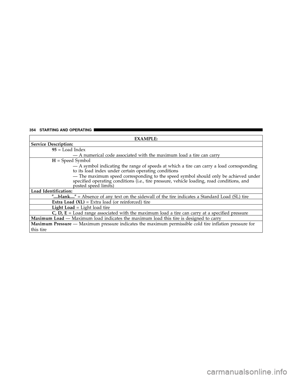
EXAMPLE:
Service Description: 95= Load Index
— A numerical code associated with the maximum load a tire can carry
H = Speed Symbol
— A symbol indicating the range of speeds at which a tire can carry a load corresponding
to its load index under certain operating conditions
— The maximum speed corresponding to the speed symbol should only be achieved under
specified operating conditions (i.e., tire pressure, vehicle loading, road conditions, and
posted speed limits)
Load Identification: �....blank....� = Absence of any text on the sidewall of the tire indicates a Standard Load (SL) tire
Extra Load (XL) = Extra load (or reinforced) tire
Light Load = Light load tire
C, D, E = Load range associated with the maximum load a tire can carry at a specified pressure
Maximum Load — Maximum load indicates the maximum load this tire is designed to carry
Maximum Pressure — Maximum pressure indicates the maximum permissible cold tire inflation pressure for
this tire
354 STARTING AND OPERATING
Page 357 of 538
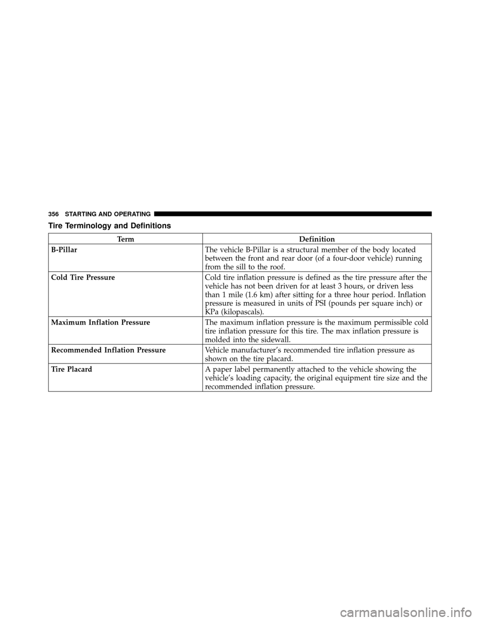
Tire Terminology and Definitions
TermDefinition
B-Pillar The vehicle B-Pillar is a structural member of the body located
between the front and rear door (of a four-door vehicle) running
from the sill to the roof.
Cold Tire Pressure Cold tire inflation pressure is defined as the tire pressure after the
vehicle has not been driven for at least 3 hours, or driven less
than 1 mile (1.6 km) after sitting for a three hour period. Inflation
pressure is measured in units of PSI (pounds per square inch) or
KPa (kilopascals).
Maximum Inflation Pressure The maximum inflation pressure is the maximum permissible cold
tire inflation pressure for this tire. The max inflation pressure is
molded into the sidewall.
Recommended Inflation Pressure Vehicle manufacturer’s recommended tire inflation pressure as
shown on the tire placard.
Tire Placard A paper label permanently attached to the vehicle showing the
vehicle’s loading capacity, the original equipment tire size and the
recommended inflation pressure.
356 STARTING AND OPERATING
Page 358 of 538
Tire Loading and Tire Pressure
Tire Placard Location
NOTE:The proper cold tire inflation pressure is listed
on the driver’s side B-Pillar.
Tire and Loading Information Placard
This placard tells you important information about
the:
1) number of people that can be carried in the vehicle
2) total weight your vehicle can carry
Tire Placard Location
Tire and Loading Information Placard
5
STARTING AND OPERATING 357
Page 359 of 538
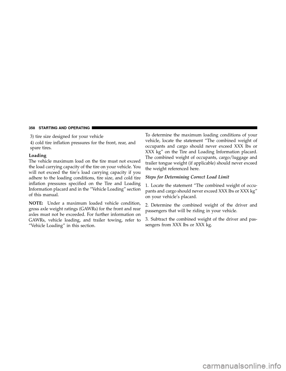
3) tire size designed for your vehicle
4) cold tire inflation pressures for the front, rear, and
spare tires.
Loading
The vehicle maximum load on the tire must not exceed
the load carrying capacity of the tire on your vehicle. You
will not exceed the tire’s load carrying capacity if you
adhere to the loading conditions, tire size, and cold tire
inflation pressures specified on the Tire and Loading
Information placard and in the “Vehicle Loading” section
of this manual.
NOTE:Under a maximum loaded vehicle condition,
gross axle weight ratings (GAWRs) for the front and rear
axles must not be exceeded. For further information on
GAWRs, vehicle loading, and trailer towing, refer to
“Vehicle Loading” in this section. To determine the maximum loading conditions of your
vehicle, locate the statement “The combined weight of
occupants and cargo should never exceed XXX lbs or
XXX kg” on the Tire and Loading Information placard.
The combined weight of occupants, cargo/luggage and
trailer tongue weight (if applicable) should never exceed
the weight referenced here.
Steps for Determining Correct Load Limit
1. Locate the statement “The combined weight of occu-
pants and cargo should never exceed XXX lbs or XXX kg”
on your vehicle’s placard.
2. Determine the combined weight of the driver and
passengers that will be riding in your vehicle.
3. Subtract the combined weight of the driver and pas-
sengers from XXX lbs or XXX kg.
358 STARTING AND OPERATING