Page 322 of 538
Winter Operation
To ensure the best possible heater and defroster perfor-
mance, make sure the engine cooling system is function-
ing properly and the proper amount, type, and concen-
tration of coolant is used. Refer to “Maintenance
Procedures” in “Maintaining Your Vehicle” for proper
coolant selection. Use of the air RECIRCULATION mode
during Winter months is not recommended, because it
may cause window fogging.
Vacation/Storage
Before you store your vehicle, or keep it out of service
(i.e., vacation) for two weeks or more, run the air
conditioning system at idle for about five minutes, in
fresh air with the blower setting on high. This will ensure
adequate system lubrication to minimize the possibility
of compressor damage when the system is started again.
Window Fogging
Vehicle windows tend to fog on the inside in mild, rainy
and/or humid weather. To clear the windows, select
DEFROST or MIX mode and increase the front blower
speed. Do not use the RECIRCULATION mode without
A/C for long periods, as fogging may occur.
Outside Air Intake
Make sure the air intake, located directly in front of the
windshield, is free of obstructions such as leaves. Leaves
collected in the air intake may reduce airflow, and if they
enter the plenum they could plug the water drains. In
Winter months make sure the air intake is clear of ice,
slush and snow.4
UNDERSTANDING YOUR INSTRUMENT PANEL 321
Page 332 of 538
Brake/Transmission Interlock System
This vehicle is equipped with a Brake Transmission Shift
Interlock System (BTSI) that holds the shift lever in the
PARK position when the ignition switch is in the LOCK
position. To move the shift lever out of the PARK
position, the ignition switch must be turned to any other
switch position (ACC, ON, or START) (engine running or
not) and the brake pedal must be pressed.
Automatic Transmission Ignition Interlock System
For electrical system malfunctions, there is an override
for the interlock system. In order to override this system,
remove the cover located to the top right of the shift lever
in the instrument panel. The override can be activated by
pressing the white-colored tab, which can be accessed
through the hole in the instrument panel. While the
override is pressed, the shift lever can be moved out of
the PARK position without pressing the brake pedal.
After operation, return the cover to its original position.This system prevents the key fob from being removed
unless the shift lever is in PARK. It also prevents moving
the shift lever out of PARK, unless the key fob is in the
ACC/ON position, and the brake pedal is pressed.
NOTE:
If a malfunction occurs, the system will trap the
key fob in the ignition cylinder to warn you that this
safety feature is inoperable. The engine can be started
and stopped but the key fob cannot be removed until you
obtain service.Four-Speed or Six-Speed Automatic
Transmission
NOTE: Under extreme cold temperatures (-10°F (-23°C)
and when in DRIVE, transmission operation may be
briefly limited to only second gear operation. Normal
operation will resume once the transmission temperature
has risen to a suitable level.
5
STARTING AND OPERATING 331
Page 338 of 538
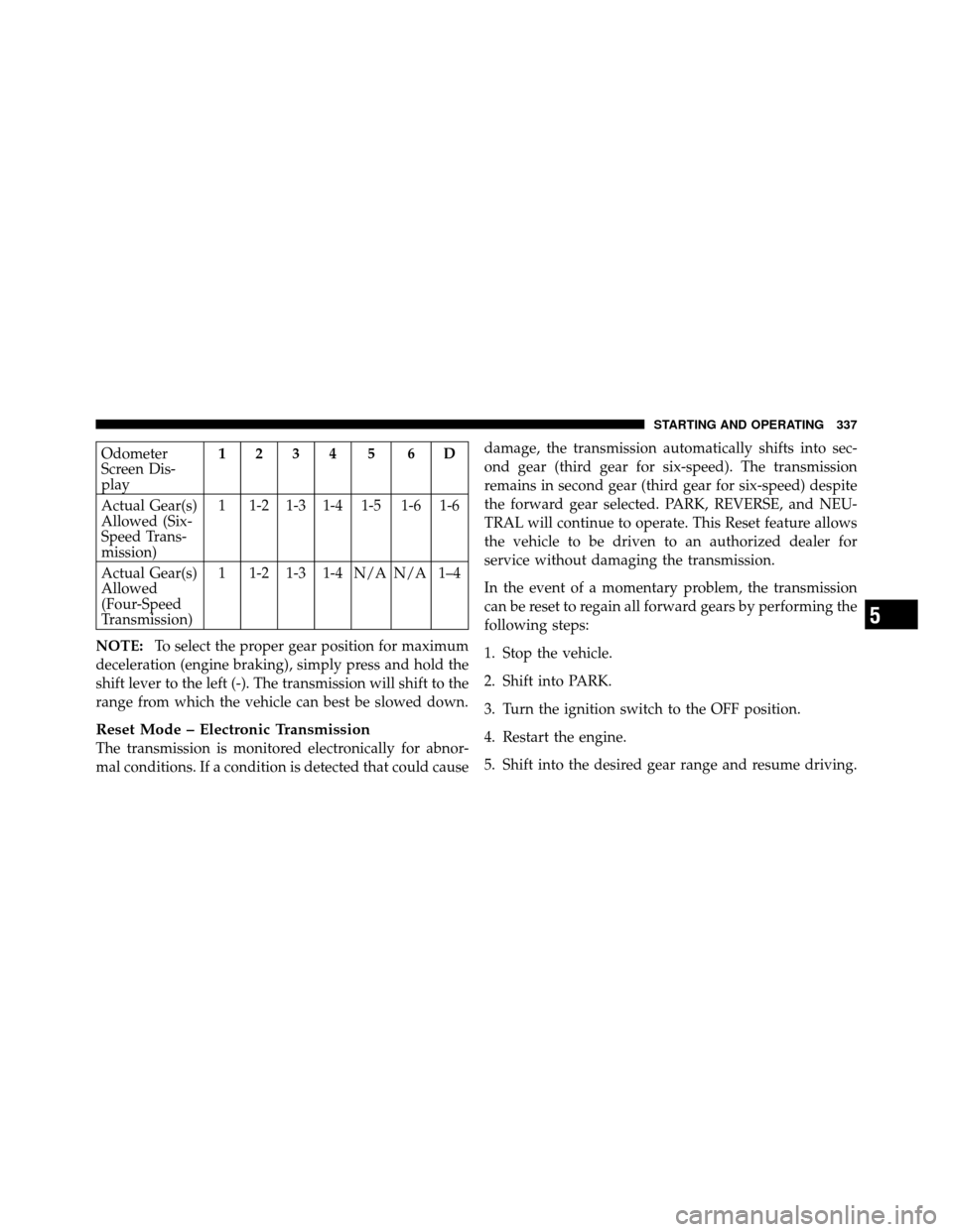
Odometer
Screen Dis-
play1234 5 6D
Actual Gear(s)
Allowed (Six-
Speed Trans-
mission) 1 1-2 1-3 1-4 1-5 1-6 1-6
Actual Gear(s)
Allowed
(Four-Speed
Transmission) 1 1-2 1-3 1-4 N/A N/A 1–4
NOTE: To select the proper gear position for maximum
deceleration (engine braking), simply press and hold the
shift lever to the left (-). The transmission will shift to the
range from which the vehicle can best be slowed down.
Reset Mode – Electronic Transmission
The transmission is monitored electronically for abnor-
mal conditions. If a condition is detected that could cause damage, the transmission automatically shifts into sec-
ond gear (third gear for six-speed). The transmission
remains in second gear (third gear for six-speed) despite
the forward gear selected. PARK, REVERSE, and NEU-
TRAL will continue to operate. This Reset feature allows
the vehicle to be driven to an authorized dealer for
service without damaging the transmission.
In the event of a momentary problem, the transmission
can be reset to regain all forward gears by performing the
following steps:
1. Stop the vehicle.
2. Shift into PARK.
3. Turn the ignition switch to the OFF position.
4. Restart the engine.
5. Shift into the desired gear range and resume driving.
5
STARTING AND OPERATING 337
Page 339 of 538
NOTE:Even if the transmission can be reset, it is
recommended that you visit an authorized dealer at your
earliest possible convenience.
If the transmission cannot be reset, authorized dealer
service is required.
DRIVING ON SLIPPERY SURFACES
Acceleration
Rapid acceleration on snow covered, wet, or other slip-
pery surfaces may cause the front wheels to pull errati-
cally to the right or left. This phenomenon occurs when
there is a difference in the surface traction under the front
(driving) wheels.
WARNING!
Rapid acceleration on slippery surfaces is dangerous.
Unequal traction can cause sudden pulling of the
front wheels. You could lose control of the vehicle
and possibly have an accident. Accelerate slowly and
carefully whenever there is likely to be poor traction
(ice, snow, wet mud, loose sand, etc.).
Traction
When driving on wet or slushy roads, it is possible for a
layer of water to build up between the tire and road
surface. This is known as hydroplaning and may cause
partial or complete loss of vehicle control and stopping
ability. To reduce this possibility, the following precau-
tions should be observed:
1. Slow down during rainstorms or when roads are
slushy.
338 STARTING AND OPERATING
Page 343 of 538
•Upon initial start-up in cold weather, the power steer-
ing pump may make noise for a short amount of time.
This is due to the cold, thick fluid in the steering
system. This noise should be considered normal, and it
does not in any way damage the steering system.
WARNING!
Continued operation with reduced power steering
assist could pose a safety risk to yourself and others.
Service should be obtained as soon as possible.
CAUTION!
Prolonged operation of the steering system at the end
of the steering wheel travel will increase the steering
fluid temperature and it should be avoided when
possible. Damage to the power steering pump may
occur.
Power Steering Fluid Check
Checking the power steering fluid level at a defined
service interval is not required. The fluid should only be
checked if a leak is suspected, abnormal noises are
apparent, and/or the system is not functioning as antici-
pated. Coordinate inspection efforts through an autho-
rized dealer.
CAUTION!
Do not use chemical flushes in your power steering
system as the chemicals can damage your power
steering components. Such damage is not covered by
the New Vehicle Limited Warranty.
342 STARTING AND OPERATING
Page 346 of 538
WARNING! (Continued)
•Always fully apply the parking brake when leav-
ing your vehicle, or it may roll and cause damage
or injury. Also be certain to leave the transmission
in PARK. Failure to do so may allow the vehicle to
roll and cause damage or injury.
CAUTION!
If the Brake System Warning Light remains on with
the parking brake released, a brake system malfunc-
tion is indicated. Have the brake system serviced by
an authorized dealer immediately.
ANTI-LOCK BRAKE SYSTEM (ABS)
The Anti-Lock Brake System (ABS) provides increased
vehicle stability and brake performance under most
braking conditions. The system operates with a separatecomputer to modulate hydraulic pressure to prevent
wheel lock-up and help avoid skidding on slippery
surfaces.
ABS is activated during braking under certain road or
stopping conditions. ABS-inducing conditions can in-
clude ice, snow, gravel, bumps, railroad tracks, loose
debris, or panic stops.
You may experience the following when the brake system
goes into anti-lock:
•The ABS motor running (it may continue to run for a
short time after the stop)
•A clicking sound of solenoid valves
•Brake pedal pulsations
•A slight drop or fall away of the brake pedal at the end
of the stop
5
STARTING AND OPERATING 345
Page 348 of 538
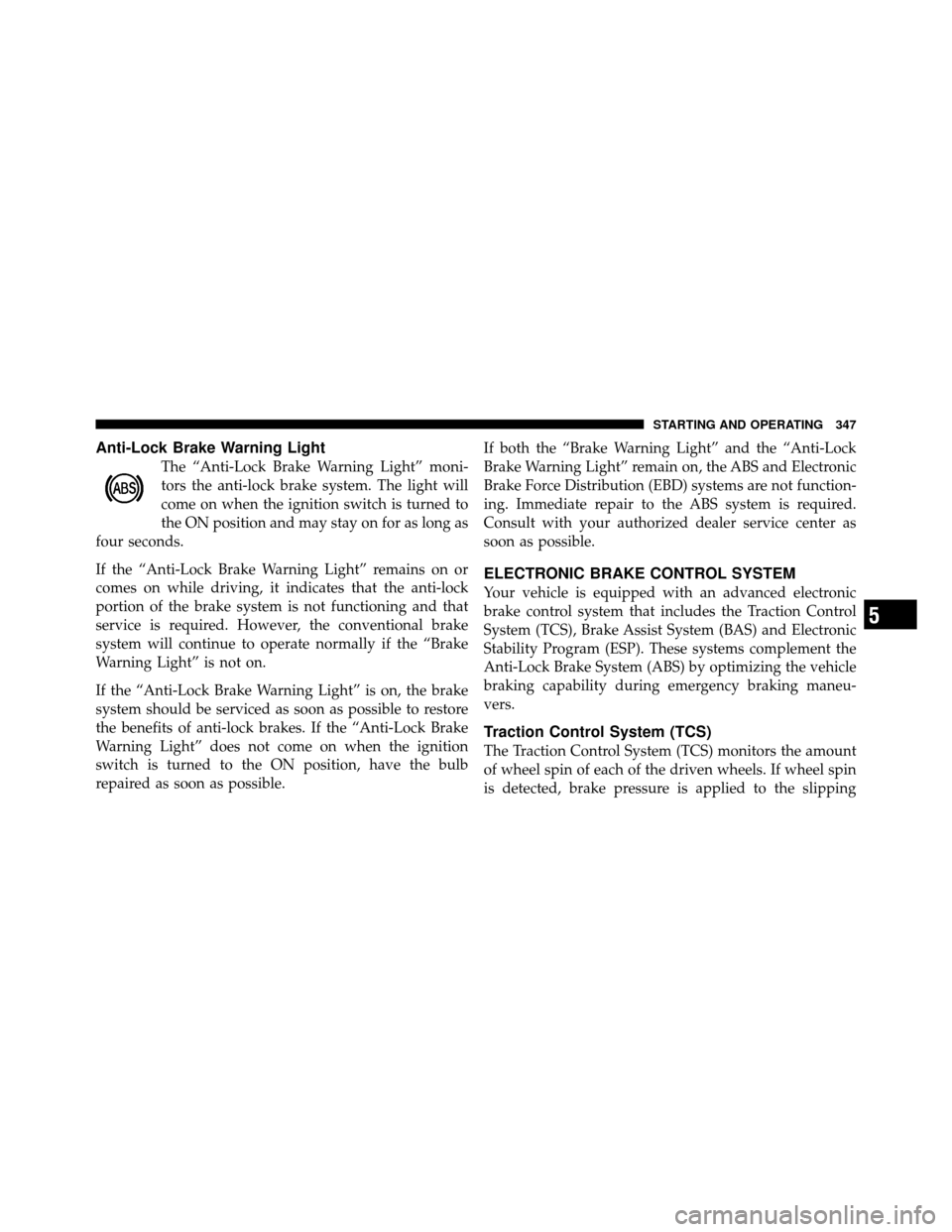
Anti-Lock Brake Warning Light
The “Anti-Lock Brake Warning Light” moni-
tors the anti-lock brake system. The light will
come on when the ignition switch is turned to
the ON position and may stay on for as long as
four seconds.
If the “Anti-Lock Brake Warning Light” remains on or
comes on while driving, it indicates that the anti-lock
portion of the brake system is not functioning and that
service is required. However, the conventional brake
system will continue to operate normally if the “Brake
Warning Light” is not on.
If the “Anti-Lock Brake Warning Light” is on, the brake
system should be serviced as soon as possible to restore
the benefits of anti-lock brakes. If the “Anti-Lock Brake
Warning Light” does not come on when the ignition
switch is turned to the ON position, have the bulb
repaired as soon as possible. If both the “Brake Warning Light” and the “Anti-Lock
Brake Warning Light” remain on, the ABS and Electronic
Brake Force Distribution (EBD) systems are not function-
ing. Immediate repair to the ABS system is required.
Consult with your authorized dealer service center as
soon as possible.
ELECTRONIC BRAKE CONTROL SYSTEM
Your vehicle is equipped with an advanced electronic
brake control system that includes the Traction Control
System (TCS), Brake Assist System (BAS) and Electronic
Stability Program (ESP). These systems complement the
Anti-Lock Brake System (ABS) by optimizing the vehicle
braking capability during emergency braking maneu-
vers.
Traction Control System (TCS)
The Traction Control System (TCS) monitors the amount
of wheel spin of each of the driven wheels. If wheel spin
is detected, brake pressure is applied to the slipping
5
STARTING AND OPERATING 347
Page 353 of 538
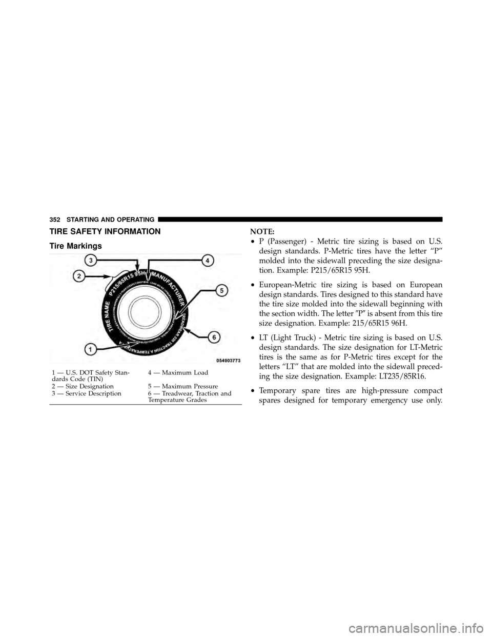
TIRE SAFETY INFORMATION
Tire MarkingsNOTE:
•P (Passenger) - Metric tire sizing is based on U.S.
design standards. P-Metric tires have the letter “P”
molded into the sidewall preceding the size designa-
tion. Example: P215/65R15 95H.
•European-Metric tire sizing is based on European
design standards. Tires designed to this standard have
the tire size molded into the sidewall beginning with
the section width. The letter�P�is absent from this tire
size designation. Example: 215/65R15 96H.
•LT (Light Truck) - Metric tire sizing is based on U.S.
design standards. The size designation for LT-Metric
tires is the same as for P-Metric tires except for the
letters “LT” that are molded into the sidewall preced-
ing the size designation. Example: LT235/85R16.
•Temporary spare tires are high-pressure compact
spares designed for temporary emergency use only.
1 — U.S. DOT Safety Stan-
dards Code (TIN) 4 — Maximum Load
2 — Size Designation 5 — Maximum Pressure
3 — Service Description 6 — Treadwear, Traction and Temperature Grades
352 STARTING AND OPERATING