2010 CHRYSLER TOWN AND COUNTRY ESP
[x] Cancel search: ESPPage 199 of 538
2. This device must accept any interference that may be
received including interference that may cause undesired
operation.
NOTE:
•The transmitter has been tested and it complies with
FCC and IC rules. Changes or modifications not
expressly approved by the party responsible for com-
pliance could void the user ’s authority to operate the
device.
•The term IC before the certification/registration num-
ber only signifies that Industry Canada technical
specifications were met.
POWER SUNROOF — IF EQUIPPED
The power sunroof control switch is located in the front
overhead console.
The sunroof panel tilts upward at the rear for ventilation
or slides rearward under the roof.
Power Sunroof Operation
Opening the Sunroof Manually
Press the switch rearward and hold, and the sunroof will
open automatically from any position. The sunroof will
open fully, then stop automatically. During this opera-
tion, any release of the sunroof switch will stop the
sunroof.
WARNING!
In an accident, there is greater risk of being thrown
from a vehicle with an open sunroof. You could also
be seriously injured or killed. Always fasten your
seat belt properly and make sure all passengers are
properly secured.
198 UNDERSTANDING THE FEATURES OF YOUR VEHICLE
Page 224 of 538
NOTE:To help control wind noise when installing the
crossbars ensure the embossed arrow is facing the front
of the vehicle. When the crossbars are not in use, the front
crossbar should be fastened just forward of the middle
support and the rear crossbar should be fastened at the
rearmost position of the side rails. This will help reduce
the amount of wind noise when the crossbars are not in
use.
The tie down holes on the crossbar ends should always
be used to tie down the load. Check the straps frequently
to be sure that the load remains securely attached.
CAUTION!
•Crossbars should remain equally spaced or paral-
lel at any luggage rack position for proper func-
tion. Noncompliance could result in damage to the
luggage rack, cargo and/or vehicle.
(Continued)
CAUTION! (Continued)
•To avoid damage to the roof rack and vehicle, do
not exceed the maximum roof rack load capacity of
150 lbs (68 kg). Always distribute heavy loads as
evenly as possible and secure the load appropri-
ately.
•Long loads which extend over the windshield,
such as wood panels or surfboards, or loads with
large frontal area should be secured to both the
front and rear of the vehicle.
•Travel at reduced speeds and turn corners care-
fully when carrying large or heavy loads on the
roof rack. Wind forces, due to natural causes or
nearby truck traffic, can add sudden upward lift to
a load. This is especially true on large flat loads
and may result in damage to the cargo or your
vehicle.
3
UNDERSTANDING THE FEATURES OF YOUR VEHICLE 223
Page 235 of 538
vehicle is experiencing a problem with the charging
system. Obtain SERVICE IMMEDIATELY. See an autho-
rized dealer.
If jump starting is required, refer to “Jump Starting
Procedures” in “What To Do In Emergencies”.
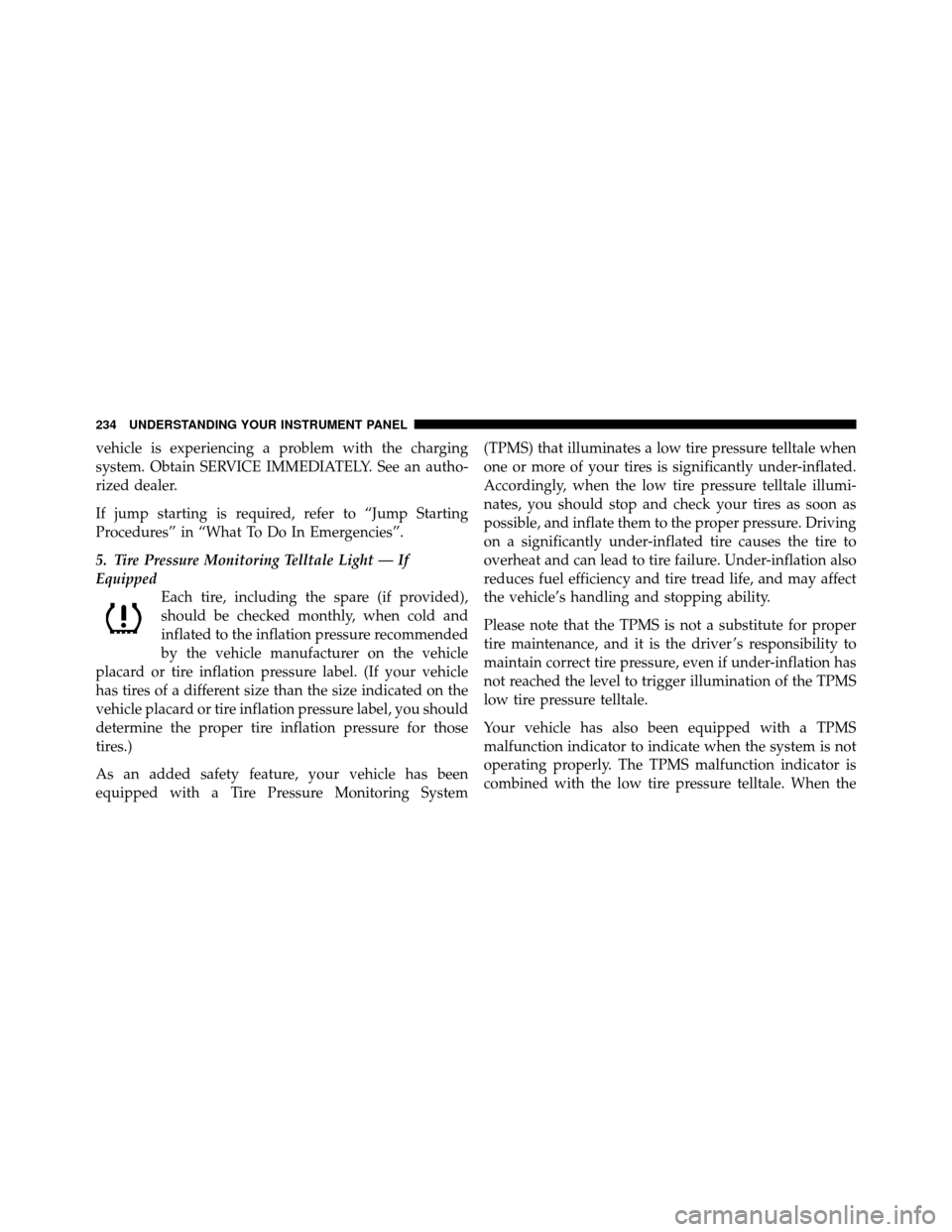
5. Tire Pressure Monitoring Telltale Light — If
EquippedEach tire, including the spare (if provided),
should be checked monthly, when cold and
inflated to the inflation pressure recommended
by the vehicle manufacturer on the vehicle
placard or tire inflation pressure label. (If your vehicle
has tires of a different size than the size indicated on the
vehicle placard or tire inflation pressure label, you should
determine the proper tire inflation pressure for those
tires.)
As an added safety feature, your vehicle has been
equipped with a Tire Pressure Monitoring System (TPMS) that illuminates a low tire pressure telltale when
one or more of your tires is significantly under-inflated.
Accordingly, when the low tire pressure telltale illumi-
nates, you should stop and check your tires as soon as
possible, and inflate them to the proper pressure. Driving
on a significantly under-inflated tire causes the tire to
overheat and can lead to tire failure. Under-inflation also
reduces fuel efficiency and tire tread life, and may affect
the vehicle’s handling and stopping ability.
Please note that the TPMS is not a substitute for proper
tire maintenance, and it is the driver ’s responsibility to
maintain correct tire pressure, even if under-inflation has
not reached the level to trigger illumination of the TPMS
low tire pressure telltale.
Your vehicle has also been equipped with a TPMS
malfunction indicator to indicate when the system is not
operating properly. The TPMS malfunction indicator is
combined with the low tire pressure telltale. When the
234 UNDERSTANDING YOUR INSTRUMENT PANEL
Page 238 of 538
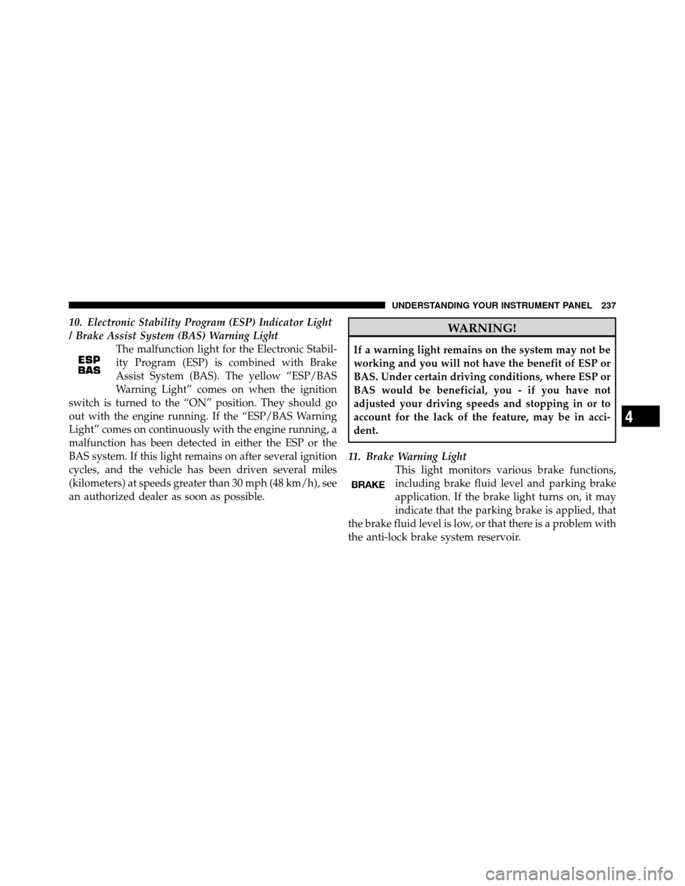
10. Electronic Stability Program (ESP) Indicator Light
/ Brake Assist System (BAS) Warning LightThe malfunction light for the Electronic Stabil-
ity Program (ESP) is combined with Brake
Assist System (BAS). The yellow “ESP/BAS
Warning Light” comes on when the ignition
switch is turned to the “ON” position. They should go
out with the engine running. If the “ESP/BAS Warning
Light” comes on continuously with the engine running, a
malfunction has been detected in either the ESP or the
BAS system. If this light remains on after several ignition
cycles, and the vehicle has been driven several miles
(kilometers) at speeds greater than 30 mph (48 km/h), see
an authorized dealer as soon as possible.WARNING!
If a warning light remains on the system may not be
working and you will not have the benefit of ESP or
BAS. Under certain driving conditions, where ESP or
BAS would be beneficial, you - if you have not
adjusted your driving speeds and stopping in or to
account for the lack of the feature, may be in acci-
dent.
11. Brake Warning Light This light monitors various brake functions,
including brake fluid level and parking brake
application. If the brake light turns on, it may
indicate that the parking brake is applied, that
the brake fluid level is low, or that there is a problem with
the anti-lock brake system reservoir.
4
UNDERSTANDING YOUR INSTRUMENT PANEL 237
Page 239 of 538
If the light remains on when the parking brake has been
disengaged, and the fluid level is at the full mark on the
master cylinder reservoir, it indicates a possible brake
hydraulic system malfunction or that a problem with the
Brake Booster has been detected by the Anti-Lock Brake
System (ABS) / Electronic Stability Program (ESP) sys-
tem. In this case, the light will remain on until the
condition has been corrected. If the problem is related to
the brake booster, the ABS pump will run when applying
the brake and a brake pedal pulsation may be felt during
each stop.
The dual brake system provides a reserve braking capac-
ity in the event of a failure to a portion of the hydraulic
system. A leak in either half of the dual brake system is
indicated by the Brake Warning Light, which will turn on
when the brake fluid level in the master cylinder has
dropped below a specified level.
The light will remain on until the cause is corrected.NOTE:
The light may flash momentarily during sharp
cornering maneuvers, which change fluid level condi-
tions. The vehicle should have service performed, and
the brake fluid level checked.
If brake failure is indicated, immediate repair is neces-
sary.
WARNING!
Driving a vehicle with the red brake light on is
dangerous. Part of the brake system may have failed.
It will take longer to stop the vehicle. You could have
an accident. Have the vehicle checked immediately.
Vehicles equipped with the Anti-Lock Brake System
(ABS), are also equipped with Electronic Brake Force
Distribution (EBD). In the event of an EBD failure, the
Brake Warning Light will turn on along with the ABS
Light. Immediate repair to the ABS system is required.
238 UNDERSTANDING YOUR INSTRUMENT PANEL
Page 241 of 538
14. Electronic Stability Program (ESP) Indicator Light
/ Traction Control System (TCS) Indicator LightIf this indicator light flashes during accelera-
tion, apply as little throttle as possible. While
driving, ease up on the accelerator. Adapt your
speed and driving to the prevailing road con-
ditions, and do not switch off the Electronic Stability
Program (ESP), or Traction Control System (TCS).
15. Tachometer
The red segments indicate the maximum permissible
engine revolutions per minute (RPM x 1000) for each gear
range. Before reaching the red area, ease up on the
accelerator.
16. High Beam Indicator This indicator shows that the high beam head-
lights are on. Push the multifunction lever forward
to switch the headlights to high beam, and pull toward
yourself (normal position) to return to low beam. 17. Front Fog Light Indicator — If Equipped
This indicator will illuminate when the front fog
lights are on.
18. Seat Belt Reminder Light When the ignition switch is first turned ON, this
light will turn on for five to eight seconds as a bulb
check. During the bulb check, if the driver’s seat
belt is unbuckled, a chime will sound. After the bulb
check or when driving, if the driver’s seat belt remains
unbuckled, the Seat Belt Reminder Light will illuminate
and the chime will sound. Refer to “Occupant Restraints”
in “Things To Know Before Starting Your Vehicle” for
further information.
19. Malfunction Indicator Light (MIL) The Malfunction Indicator Light (MIL) is part of
an onboard diagnostic system, called OBD, that
monitors engine and automatic transmission con-
trol systems. The light will illuminate when the key is in
240 UNDERSTANDING YOUR INSTRUMENT PANEL
Page 259 of 538
2. Press and hold the compass button for approximately
two seconds.
3. Press the STEP button until “Compass Variance” mes-
sage, and the last variance zone number, displays in the
EVIC.
4. Press and release the STEP button until the proper
variance zone is selected, according to the map.
5. Press and release the compass button to exit.
Personal Settings (Customer-Programmable
Features)
Personal Settings allows you to set and recall features
when the transmission is in PARK. If the transmission is
out of PARK or the vehicle begins moving, a warning
messagePERSONAL SETTING NOT AVAILABLE ,
followed in three seconds by, VEHICLE NOT IN PARK.
Press and release the MENU button until Personal Set-
tings displays in the EVIC. Use the Step button to display one of the following
choices.
Language
When in this display you may select one of five lan-
guages for all display nomenclature, including the trip
functions and the navigation system (if equipped). Press
the RESET button while in this display to select English,
Spanish (Español), French (Français), Italian (Italiano),
German (Deutsch), and Dutch (Nederlands). Then, as
you continue, the information will display in the selected
language.
Auto Door Locks
When ON is selected, all doors will lock automatically
when the vehicle reaches a speed of 15 mph (24 km/h).
To make your selection, press and release the RESET
button until ON or OFF appears.
258 UNDERSTANDING YOUR INSTRUMENT PANEL
Page 271 of 538
Push the rotary TUNE/SCROLL control knob again to
exit setting tone, balance, and fade.
AM/FM Button
Press the buttons to select either AM or FM mode.
SET/RND Button — To Set the Pushbutton
Memory
When you are receiving a station that you wish to
commit to pushbutton memory, press the SET/RND
button. The symbol SET 1 will now show in the display
window. Select the button (1 to 6) you wish to lock onto
this station and press and release that button. If a button
is not selected within five seconds after pressing the
SET/RND button, the station will continue to play but
will not be stored into pushbutton memory.You may add a second station to each pushbutton by
repeating the above procedure with this exception: Press
the SET/RND button twice and SET 2 will show in the
display window. Each button can be set for SET 1 and
SET 2 in both AM and FM. This allows a total of 12 AM
and 12 FM stations to be stored into pushbutton memory.
The stations stored in SET 2 memory can be selected by
pressing the pushbutton twice.
Every time a preset button is used, a corresponding
button number will display.
Buttons 1 - 6
These buttons tune the radio to the stations that you
commit to pushbutton memory (12 AM and 12 FM
stations).
DISC Button
Pressing the DISC button will allow you to switch from
AM/FM modes to Disc modes.
270 UNDERSTANDING YOUR INSTRUMENT PANEL