Page 256 of 436

ABS is activated during braking under certain road or
stopping conditions. ABS-inducing conditions can in-
clude ice, snow, gravel, bumps, railroad tracks, loose
debris, or panic stops.
You also may experience the following when the brake
system goes into anti-lock:
•The ABS motor running (it may continue to run for a
short time after the stop),
•the clicking sound of solenoid valves,
•brake pedal pulsations,
•and a slight drop or fall away of the brake pedal at the
end of the stop.
These are all normal characteristics of ABS.
WARNING!
The Anti-Lock Brake System contains sophisticated
electronic equipment that may be susceptible to
interference caused by improperly installed or high
output radio transmitting equipment. This interfer-
ence can cause possible loss of anti-lock braking
capability. Installation of such equipment should be
performed by qualified professionals.
All vehicle wheels and tires must be the same size and
type, and tires must be properly inflated to produce
accurate signals for the computer.
ELECTRONIC BRAKE CONTROL SYSTEM
Your vehicle may be equipped with an optional ad-
vanced electronic brake control system that includes
Anti-Lock Brake System (ABS), Traction Control System
(TCS), Brake Assist System (BAS), Hill Start Assist (HSA),
and Electronic Stability Control (ESC). All systems work
256 STARTING AND OPERATING
Page 257 of 436

together to enhance vehicle stability and control in vari-
ous driving conditions and are commonly referred to as
ESC.
Anti-Lock Brake System (ABS)
This system aids the driver in maintaining vehicle control
under adverse braking conditions. The system controls
hydraulic brake pressure to prevent wheel lock-up and
help avoid skidding on slippery surfaces during braking.
Refer to “Anti-Lock Brake System” in this section of the
manual for more information about ABS.
Traction Control System (TCS)
This system monitors the amount of wheel spin of each of
the driven wheels. If wheel spin is detected, brake
pressure is applied to the slipping wheel(s) and engine
power is reduced to provide enhanced acceleration and
stability. A feature of the TCS system functions similar to
a limited slip differential and controls the wheel spin
across a driven axle. If one wheel on a driven axle isspinning faster than the other, the system will apply the
brake of the spinning wheel. This will allow more engine
torque to be applied to the wheel that is not spinning.
This feature remains active even if TCS and ESC are in
the “Partial Off” mode. Refer to “Electronic Stability
Control (ESC)” in this section of this manual.
Brake Assist System (BAS)
The BAS is designed to optimize the vehicle’s braking
capability during emergency braking maneuvers. The sys-
tem detects an emergency braking situation by sensing the
rate and amount of brake application and then applies
optimum pressure to the brakes. This can help reduce
braking distances. The BAS complements the Anti-Lock
Brake System (ABS). Applying the brakes very quickly
results in the best BAS assistance. To receive the benefit of
the system, you must apply continuous braking pressure
during the stopping sequence. Do not reduce brake pedal
pressure unless braking is no longer desired. Once the
brake pedal is released, the BAS is deactivated.
5
STARTING AND OPERATING 257
Page 264 of 436

TIRE SAFETY INFORMATION
Tire MarkingsNOTE:
•P (Passenger) - Metric tire sizing is based on U.S.
design standards. P-Metric tires have the letter “P”
molded into the sidewall preceding the size designa-
tion. Example: P215/65R15 95H.
•European-Metric tire sizing is based on European
design standards. Tires designed to this standard have
the tire size molded into the sidewall beginning with
the section width. The letter�P�is absent from this tire
size designation. Example: 215/65R15 96H.
•LT (Light Truck) - Metric tire sizing is based on U.S.
design standards. The size designation for LT-Metric
tires is the same as for P-Metric tires except for the
letters “LT” that are molded into the sidewall preced-
ing the size designation. Example: LT235/85R16.
•Temporary spare tires are high-pressure compact
spares designed for temporary emergency use only.
Tires designed to this standard have the letter “T”
molded into the sidewall preceding the size designa-
tion. Example: T145/80D18 103M.1 — U.S. DOT Safety Stan-
dards Code (TIN) 4 — Maximum Load
2 — Size Designation 5 — Maximum Pressure
3 — Service Description 6 — Treadwear, Traction and Temperature Grades
264 STARTING AND OPERATING
Page 266 of 436

EXAMPLE:
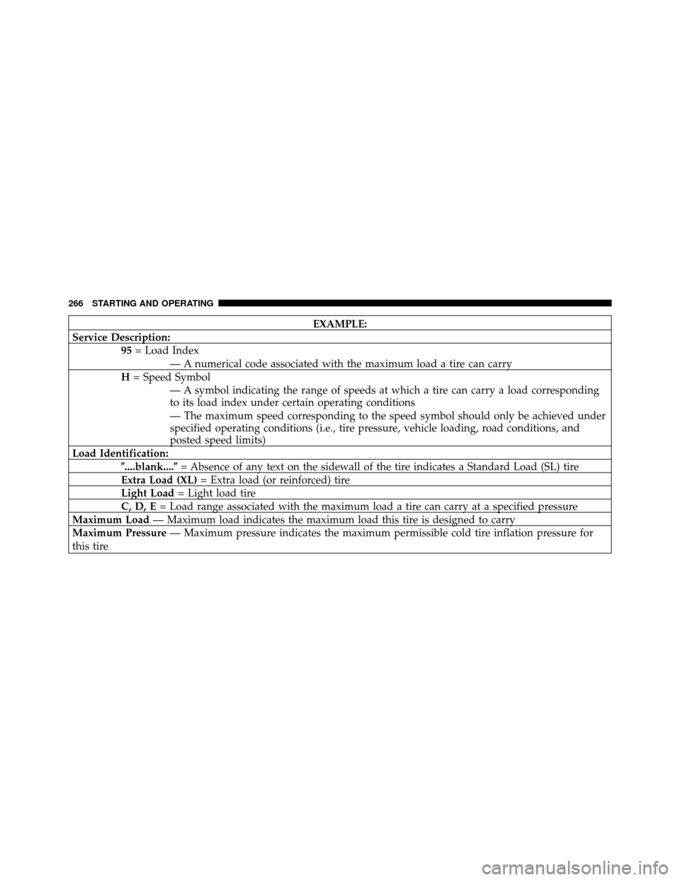
Service Description: 95= Load Index
— A numerical code associated with the maximum load a tire can carry
H = Speed Symbol
— A symbol indicating the range of speeds at which a tire can carry a load corresponding
to its load index under certain operating conditions
— The maximum speed corresponding to the speed symbol should only be achieved under
specified operating conditions (i.e., tire pressure, vehicle loading, road conditions, and
posted speed limits)
Load Identification: �....blank....� = Absence of any text on the sidewall of the tire indicates a Standard Load (SL) tire
Extra Load (XL) = Extra load (or reinforced) tire
Light Load = Light load tire
C, D, E = Load range associated with the maximum load a tire can carry at a specified pressure
Maximum Load — Maximum load indicates the maximum load this tire is designed to carry
Maximum Pressure — Maximum pressure indicates the maximum permissible cold tire inflation pressure for
this tire
266 STARTING AND OPERATING
Page 350 of 436
5. Disengage the two retaining tabs that secure the filter
cover to the HVAC housing and remove the cover.
6. Remove the A/C Air Filter by pulling it straight out of
the housing.7. Install the A/C Air Filter with the arrow on the filter
pointing toward the floor. When installing the filter
cover, make sure the retaining tabs fully engage the
cover.
CAUTION!
The A/C Air Filter is labeled with an arrow to
indicate airflow direction through the filter. Failure
to install the filter properly will result in the need to
replace it more often.
8. Reinstall the glove box door dampener and glove box.
Body Lubrication
Locks and all body pivot points, including such items as
seat tracks, door hinge pivot points and rollers, liftgate,
tailgate, sliding doors and hood hinges, should be lubri-
cated periodically with a lithium based grease, such as
MOPAR� Spray White Lube or equivalent, to assureA/C Air Filter Replacement
350 MAINTAINING YOUR VEHICLE
Page 362 of 436

WARNING! (Continued)
•To avoid contamination from foreign matter or
moisture, use only new brake fluid or fluid that
has been in a tightly closed container. Keep the
master cylinder reservoir cap secured at all times.
Brake fluid in a open container absorbs moisture
from the air resulting in a lower boiling point.
This may cause it to boil unexpectedly during hard
or prolonged braking, resulting in sudden brake
failure. This could result in a accident.
•Overfilling the brake fluid reservoir can result in
spilling brake fluid on hot engine parts, causing
the brake fluid to catch fire. Brake fluid can also
damage painted and vinyl surfaces, care should be
taken to avoid its contact with these surfaces.(Continued)
WARNING! (Continued)
•Do not allow petroleum based fluid to contami-
nate the brake fluid. Brake seal components could
be damaged, causing partial or complete brake
failure. This could result in an accident.
Automatic Transaxle
The automatic transaxle and differential assembly are
contained within a single housing.
The fluid level in the automatic transaxle should be
checked whenever the vehicle is serviced. Operation with
an improper fluid level will greatly reduce the life of the
transaxle and the fluid.
362 MAINTAINING YOUR VEHICLE
Page 368 of 436

Do not use abrasive cleaning components, solvents, steel
wool or other aggressive material to clean the lenses.
Stain Repel Fabric Cleaning Procedure — If
Equipped
Stain Repel seats may be cleaned in the following man-
ner:
•Remove as much of the stain as possible by blotting
with a clean, dry towel.
•Blot any remaining stain with a clean, damp towel.
•For tough stains, apply MOPAR�Total Clean or
equivalent, or a mild soap solution to a clean, damp
cloth and remove the stain. Use a fresh, damp towel to
remove soap residue.
•For grease stains, apply MOPAR� Multi-Purpose
Cleaner or equivalent to a clean, damp cloth and
remove the stain. Use a fresh, damp towel to remove
soap residue.
•Do not use any harsh solvents or any other form of
protectants on Stain Repel products.
Interior Care
Instrument Panel Cover
The instrument panel cover has a low glare surface,
which minimizes reflections in the windshield. Do not
use protectants or other products, which may cause
undesirable reflections. Use soap and warm water to
restore the low glare surface.
Cleaning Interior Trim
Interior Trim should be cleaned starting with a damp
cloth, a damp cloth with MOPAR� Total Clean or equiva-
lent, then MOPAR� Spot & Stain Remover or equivalent
if absolutely necessary. Do not use harsh cleaners or
Armorall. Use MOPAR� Total Clean or equivalent to
clean vinyl upholstery.
368 MAINTAINING YOUR VEHICLE
Page 375 of 436
CavityCartridge
Fuse Mini
Fuse Description
31 —10 Amp
Red —
32 30 Amp
Pink —Auto Shutdown
(ASD) Relay Feed 1
33 —10 Amp
Red Battery Feed —
Switch Bank/
Diagnostic Link
Connector/
Powertrain Control
Module (PCM)
34 30 Amp
Pink —Battery Feed —
Anti-Lock Brakes
(ABS) Module - if
equipped/
Electronic Stability
Program (ESP)
Module - If
EquippedCavity
Cartridge
Fuse Mini
Fuse Description
35 40 Amp
Green —Battery Feed —
Anti-Lock Brakes
(ABS) Module - If
Equipped/
Electronic Stability
Program (ESP)
Module - If
Equipped
7
MAINTAINING YOUR VEHICLE 375