2010 CHRYSLER SEBRING reset
[x] Cancel search: resetPage 36 of 444

Auto Window Up — If Equipped
Lift the window switch to the second detent, release, and
the window will go up automatically.
To cancel the Auto Up movement, operate the switch
either in the up or down direction and release the switch.
To close the window part way, lift the window switch to
the first detent and release it when you want the window
to stop.
NOTE:ANTI-PINCH PROTECTION
•If the window runs into any obstacle during auto-
closure, it will reverse direction and then go back
down. Remove the obstacle and use the window
switch again to close the window.
•Any impact due to rough road conditions may trigger
the auto reverse function unexpectedly during auto-
closure. If this happens, pull the switch lightly to the
first detent and hold to close window manually.
WARNING!
When the window is almost closed, there is no
anti-pinch protection. To avoid personal injury, be
sure to clear your arms, hands, fingers and all objects
from the window path before closing.
Reset Auto Up
Anytime the vehicle battery goes dead, the Auto Up
function will be disabled. To reactivate the Auto Up
feature, pull the window switch up to close the window
completely and continue to hold the switch up for an
additional two seconds after the window is closed.
2
THINGS TO KNOW BEFORE STARTING YOUR VEHICLE 35
Page 49 of 444

However if during a front impact, a secondary rear
impact occurs, the AHR may deploy based on the sever-
ity and type of the impact.CAUTION!
All occupants, including the driver, should not oper-
ate a vehicle or sit in a vehicle’s seat until the head
restraints are placed in their proper positions in order
to minimize the risk of neck injury in the event of a
collision.
NOTE: For more information on properly adjusting and
positioning the head restraint, refer to “Adjusting Active
Head Restraints” in “Understanding The Features Of
Your Vehicle”.
Resetting Active Head Restraints (AHR)
If the Active Head Restraints are triggered in a collision,
you must reset the head restraint on the driver ’s and
front passenger seat. You can recognize when the Active
Head Restraint has been triggered by the fact that they
have moved forward (as shown in step three of the
resetting procedure).
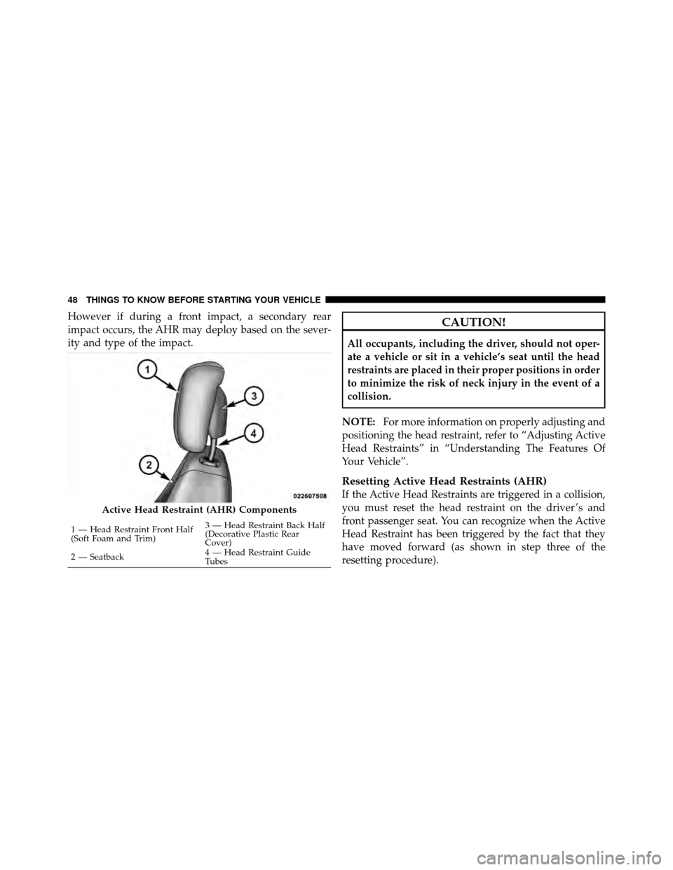
Active Head Restraint (AHR) Components
1 — Head Restraint Front Half
(Soft Foam and Trim) 3 — Head Restraint Back Half
(Decorative Plastic Rear
Cover)
2 — Seatback 4 — Head Restraint Guide
Tubes
48 THINGS TO KNOW BEFORE STARTING YOUR VEHICLE
Page 51 of 444

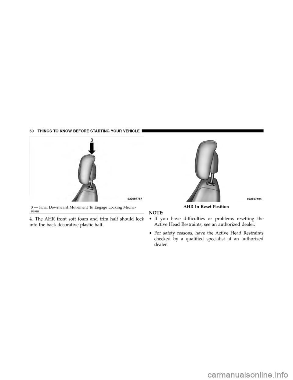
4. The AHR front soft foam and trim half should lock
into the back decorative plastic half.NOTE:•If you have difficulties or problems resetting the
Active Head Restraints, see an authorized dealer.
•For safety reasons, have the Active Head Restraints
checked by a qualified specialist at an authorized
dealer.
3 — Final Downward Movement To Engage Locking Mecha-
nismAHR In Reset Position
50 THINGS TO KNOW BEFORE STARTING YOUR VEHICLE
Page 101 of 444

•In the event of deployment of an Active Head Re-
straint, refer to “Occupant Restraints/Resetting Active
Head Restraints (AHR)” in “Things to Know Before
Starting Your Vehicle” for further information.
WARNING!
•Driving a vehicle with the head restraints removed
or improperly adjusted could cause serious injury
or death in the event of a collision. The head
restraints should always be checked prior to oper-
ating the vehicle and never adjusted while the
vehicle is in motion. Always adjust the head
restraints when the vehicle is in PARK.(Continued)
WARNING! (Continued)
•Do not place items over the top of the Active Head
Restraint, such as coats, seat covers or portable
DVD players. These items may interfere with the
operation of the Active Head Restraint in the event
of an accident and could result in serious injury or
death.
•Active Head Restraints may be deployed if they
are struck by an object such as a hand, foot or loose
cargo. To avoid accidental deployment of the Ac-
tive Head Restraint ensure that all cargo is se-
cured, as loose cargo could contact the Active Head
Restraint during sudden stops. Failure to follow
this warning could cause personal injury if the
Active Head Restraint is deployed.
100 UNDERSTANDING THE FEATURES OF YOUR VEHICLE
Page 118 of 444

ELECTRONIC SPEED CONTROL
When engaged, the Electronic Speed Control takes over
the accelerator operation at speeds greater than 25 mph
(40 km/h).
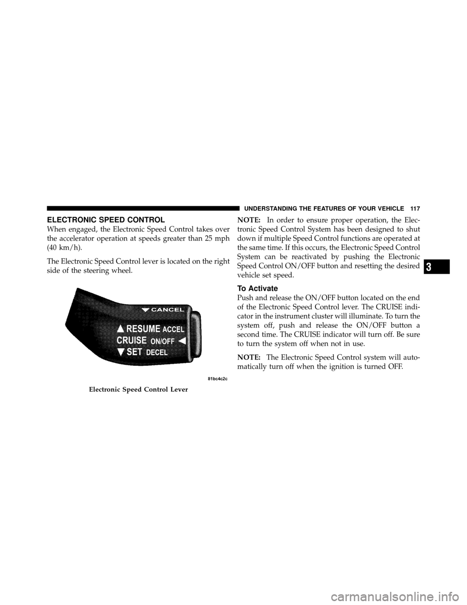
The Electronic Speed Control lever is located on the right
side of the steering wheel.NOTE:
In order to ensure proper operation, the Elec-
tronic Speed Control System has been designed to shut
down if multiple Speed Control functions are operated at
the same time. If this occurs, the Electronic Speed Control
System can be reactivated by pushing the Electronic
Speed Control ON/OFF button and resetting the desired
vehicle set speed.
To Activate
Push and release the ON/OFF button located on the end
of the Electronic Speed Control lever. The CRUISE indi-
cator in the instrument cluster will illuminate. To turn the
system off, push and release the ON/OFF button a
second time. The CRUISE indicator will turn off. Be sure
to turn the system off when not in use.
NOTE: The Electronic Speed Control system will auto-
matically turn off when the ignition is turned OFF.
Electronic Speed Control Lever
3
UNDERSTANDING THE FEATURES OF YOUR VEHICLE 117
Page 150 of 444

12. Tachometer
The silver area of the scale shows the permissible engine
revolutions-per-minute (RPM x 1000) for each gear range.
Before reaching the red area, ease up on the accelerator to
prevent engine damage.
13. Shift Lever Indicator
The Shift Lever Indicator is self-contained within the
instrument cluster. It displays the gear position of the
automatic transmission.
NOTE:You must apply the brakes before shifting from
PARK.
14. Odometer/Trip Odometer Display Area
The odometer shows the total distance the vehicle has
been driven. U.S. Federal regulations require that upon
transfer of vehicle ownership, the seller certify to the
purchaser the correct mileage that the vehicle has been driven. If your odometer needs to be repaired or serviced,
the repair technician should leave the odometer reading
the same as it was before the repair or service. If s/he
cannot do so, then the odometer must be set at zero, and
a sticker must be placed in the door jamb stating what the
mileage was before the repair or service. It is a good idea
for you to make a record of the odometer reading before
the repair/service, so that you can be sure that it is
properly reset, or that the door jamb sticker is accurate if
the odometer must be reset at zero.
The two trip odometers show individual trip mileage. To
switch from odometer to trip odometers, press and
release the Trip Odometer button. To reset a trip odom-
eter, display the desired trip odometer to be reset then
push and hold the button until the display resets (ap-
proximately 2 seconds). Refer to “Trip Odometer Button”
for additional information.
4
UNDERSTANDING YOUR INSTRUMENT PANEL 149
Page 152 of 444

tighten the fuel filler cap properly and press the odom-
eter reset button to turn off the “gASCAP” message.
(Refer to “Onboard Diagnostic System — OBDII” in
“Maintaining Your Vehicle” for further information). If
the problem continues, the message will appear the next
time the vehicle is started. See your authorized dealer
service center as soon as possible.
CHAngE OIL
Your vehicle is equipped with an engine oil change
indicator system. The “CHAngE OIL” message will flash
in the instrument cluster odometer for approximately
12 seconds after a single chime has sounded to indicate
the next scheduled oil change interval. The engine oil
change indicator system is duty cycle based, which
means the engine oil change interval may fluctuate
dependent upon your personal driving style.
Unless reset, this message will continue to display each
time you turn the ignition switch to the “ON” position.To turn off the message temporarily, press and release the
Trip Odometer button on the instrument cluster. To reset
the oil change indicator system (after performing the
scheduled maintenance) perform the following proce-
dure:
1. Turn the ignition switch to the ON position (Do not
start the engine).
2. Fully depress the accelerator pedal slowly 3 times
within 10 seconds.
3. Turn the ignition switch to the LOCK position.
NOTE: If the indicator message illuminates when you
start the vehicle, the oil change indicator system did not
reset. If necessary repeat this procedure.
4. For vehicles equipped with the Electronic Vehicle
Information Center (EVIC), refer to “Electronic Vehicle
Information Center (EVIC)”.
4
UNDERSTANDING YOUR INSTRUMENT PANEL 151
Page 153 of 444

15. Cruise Indicator — If EquippedThis indicator shows that the Electronic Speed
Control System is ON.
16. Odometer/Trip Odometer Reset Button
Single Trip Odometer
Press and release this button to change the display from
odometer to trip odometer. The word “Trip” displays to
show that the odometer is in Trip Mode. Press and release
the button again to change the display back to the
odometer.
To reset the trip odometer, first set the display to Trip
Mode. Then push and hold the button (approximately
2 seconds) until the display resets to 0 miles (km). The
odometer must be in Trip Mode to reset the trip odom-
eter. Dual Trip Odometer — If Equipped
Press and release this button to change the display from
odometer to “Trip A.” Press and release it a second time
to change the display to “Trip B.” Press and release it a
third time to change the display back to the odometer.
To reset the trip odometer, first display the trip mileage
that you want to reset, “Trip A” or “Trip B.” Then push
and hold the button (approximately 2 seconds) until the
display resets to 0 miles (km). The odometer must be in
Trip Mode to reset the trip odometer.
17. Electronic Throttle Control (ETC) Indicator Light
This light informs you of a problem with the
Electronic Throttle Control (ETC) system. If a
problem is detected, the light will come on
while the engine is running. If the light remains
lit with the engine running, your vehicle will usually be
drivable and not need towing, however see your autho-
rized dealer for service as soon as possible.
152 UNDERSTANDING YOUR INSTRUMENT PANEL