Page 3 of 76

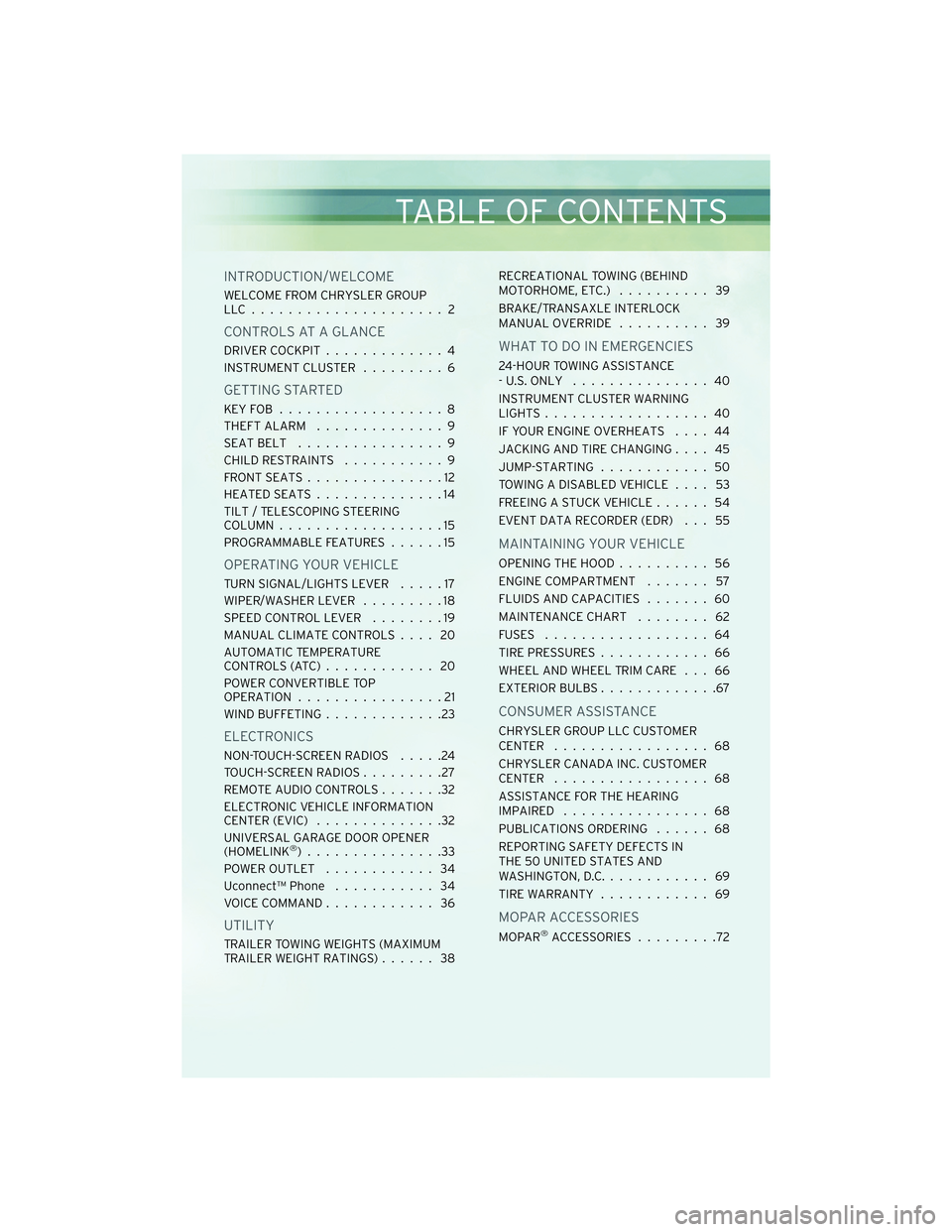
INTRODUCTION/WELCOME
WELCOME FROM CHRYSLER GROUP
LLC..................... 2
CONTROLS AT A GLANCE
DRIVER COCKPIT.............4
INSTRUMENT CLUSTER .........6
GETTING STARTED
KEYFOB ..................8
THEFT ALARM..............9
SEATBELT ................9
CHILD RESTRAINTS ...........9
FRONTSEATS...............12
HEATEDSEATS..............14
TILT / TELESCOPING STEERING
COLUMN ..................15
PROGRAMMABLE FEATURES ......15
OPERATING YOUR VEHICLE
TURN SIGNAL/LIGHTS LEVER .....17
WIPER/WASHER LEVER .........18
SPEED CONTROL LEVER ........19
MANUAL CLIMATE CONTROLS .... 20
AUTOMATIC TEMPERATURE
CONTROLS(ATC)............ 20
POWER CONVERTIBLE TOP
OPERATION ................21
WIND BUFFETING .............23
ELECTRONICS
NON-TOUCH-SCREEN RADIOS .....24
TOUCH-SCREEN RADIOS .........27
REMOTE AUDIO CONTROLS .......32
ELECTRONIC VEHICLE INFORMATION
CENTER (EVIC) ..............32
UNIVERSAL GARAGE DOOR OPENER
(HOMELINK
®)...............33
POWER OUTLET ............ 34
Uconnect™ Phone ........... 34
VOICE COMMAND ............ 36
UTILITY
TRAILER TOWING WEIGHTS (MAXIMUM
TRAILER WEIGHT RATINGS) ...... 38RECREATIONAL TOWING (BEHIND
MOTORHOME, ETC.)
.......... 39
BRAKE/TRANSAXLE INTERLOCK
MANUAL OVERRIDE .......... 39
WHAT TO DO IN EMERGENCIES
24-HOUR TOWING ASSISTANCE
- U.S. ONLY............... 40
INSTRUMENT CLUSTER WARNING
LIGHTS .................. 40
IF YOUR ENGINE OVERHEATS .... 44
JACKING AND TIRE CHANGING .... 45
JUMP-STARTING ............ 50
TOWING A DISABLED VEHICLE .... 53
FREEING A STUCK VEHICLE ...... 54
EVENT DATA RECORDER (EDR) . . . 55
MAINTAINING YOUR VEHICLE
OPENING THE HOOD .......... 56
ENGINE COMPARTMENT ....... 57
FLUIDS AND CAPACITIES ....... 60
MAINTENANCE CHART ........ 62
FUSES .................. 64
TIREPRESSURES............ 66
WHEEL AND WHEEL TRIM CARE . . . 66
EXTERIOR BULBS .............67
CONSUMER ASSISTANCE
CHRYSLER GROUP LLC CUSTOMER
CENTER ................. 68
CHRYSLER CANADA INC. CUSTOMER
CENTER ................. 68
ASSISTANCE FOR THE HEARING
IMPAIRED ................ 68
PUBLICATIONS ORDERING ...... 68
REPORTING SAFETY DEFECTS IN
THE 50 UNITED STATES AND
WASHINGTON, D.C. ........... 69
TIREWARRANTY ............ 69
MOPAR ACCESSORIES
MOPAR®ACCESSORIES .........72
TABLE OF CONTENTS
Page 17 of 76

CAUTION!
Repeated overheating of the seat could damage the heating element and/or
degrade the material of the seat.
TILT / TELESCOPING STEERING COLUMN
• The tilt/telescoping control lever is locatedbelow the steering wheel at the end of the
steering column.
• Push down on the lever to unlock the steering column.
• To tilt the steering column, move the steering wheel upward or downward as
desired. To lengthen or shorten the
steering column, pull the steering wheel
outward or push it inward as desired.
• Pull upward on the lever to lock the column firmly in place.
WARNING!
Do not adjust the steering wheel while driving. The tilt/telescoping adjustment
must be locked while driving. Adjusting the steering wheel while driving or driving
without the tilt/telescoping adjustment locked could cause the driver to lose
control of the vehicle. Failure to follow this warning may result in serious injury or
death.
PROGRAMMABLE FEATURES
Electronic Vehicle Information Center (EVIC) – If Equipped
• The EVIC can be used to program the following Personal Settings. Press and release the MENU button
until Personal Settings displays, then press the
STEP button
to scroll through the settings. Press the RESET
button
until ON or OFF appears.
• Language • Headlights With Wipers
• Auto Unlock On Exit • Headlamp Off Delay
• Remote Key Unlock • Key Off Power Delay
• Sound Horn With LOCK • ILLUMIN. Approach
• Flash Lights With LOCK • Display Units Of Measure In
15
GETTING STARTED
Page 34 of 76

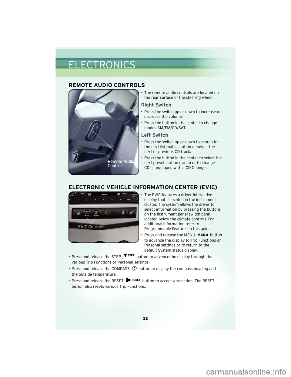
REMOTE AUDIO CONTROLS
• The remote audio controls are located onthe rear surface of the steering wheel.
Right Switch
• Press the switch up or down to increase ordecrease the volume.
• Press the button in the center to change modes AM/FM/CD/SAT.
Left Switch
• Press the switch up or down to search forthe next listenable station or select the
next or previous CD track.
• Press the button in the center to select the next preset station (radio) or to change
CDs if equipped with a CD Changer.
ELECTRONIC VEHICLE INFORMATION CENTER (EVIC)
• The EVIC features a driver interactivedisplay that is located in the instrument
cluster. The system allows the driver to
select information by pressing the buttons
on the instrument panel switch bank
located below the climate controls. For
additional information refer to
Programmable Features in this guide.
• Press and release the MENU
button
to advance the display to Trip Functions or
Personal settings or to return to the
default System status display.
• Press and release the STEP
button to advance the display through the
various Trip Functions or Personal settings.
• Press and release the COMPASS
button to display the compass heading and
the outside temperature.
• Press and release the RESET
button to accept a selection. The RESET
button also resets various Trip Functions.
ELECTRONICS
32
Page 41 of 76

RECREATIONAL TOWING
(BEHIND MOTORHOME,
ETC.)
Towing This Vehicle Behind
Another Vehicle (Flat Towing
With All Four Wheels On The
Ground)
CAUTION!
DO NOT flat tow this vehicle.
Damage to the drivetrain will result.
NOTE: If the vehicle requires towing,
make sure all four wheels are off the
ground.
BRAKE/TRANSAXLE
INTERLOCK MANUAL
OVERRIDE
• The manual override may be used in the event that the shift lever should
fail to move from PARK with the Key
Fob in the ON position and the brake
pedal pr essed.
• To operate the shift lock manual override, perform the following
steps: • Firmly apply the parking brake,
insert the ignition Key Fob and
rotate it to the ON position (do not
start engine).
• Remove the cup-holder liner.
• Insert a key, screwdriver, or finger into the front hole, then push and
hold the manual override release
lever forward.
• While holding the release lever forward, move the shift lever from
PARK to NEUTRAL. Release the
override.
• Release the parking brake.
• Have your vehicle inspected by your local authorized dealer if the shift
lock manual override has been used.
NOTE: If a malfunction occurs, the
system will trap the Key Fob in the
ignition cylinder to warn you that this
safety feature is inoperable. The
engine can be started and stopped, but
the Key Fob cannot be removed until
you obtain service.
39
UTILITY
Page 47 of 76
JACKING AND TIRE CHANGING
WARNING!
• Do not attempt to change a tire on the side of the vehicle close to moving traffic.Pull far enough off the road to avoid the danger of being hit when operating the
jack or changing the wheel.
• Getting under a jacked-up vehicle is dangerous. The vehicle could slip off the jack and fall on you. You could be crushed. Never get any part of your body
under a vehicle that is on a jack. If you need to get under a raised vehicle, take it
to a service center where it can be raised on a lift.
• The jack is designed to use as a tool for changing tires only. The jack should not be used to lift the vehicle for service purposes. The vehicle should be jacked on a
firm, level surface only. Avoid ice or slippery areas.
45
WHAT TO DO IN EMERGENCIES
Page 48 of 76
Jack Location
• The jack and jack-handle are stowed under the load floor in the trunk.
Spare Tire Stowage
• The compact spare tire is stowed under the rear load floor in the trunk.
• To remove the spare tire, lift up the load floor cover and remove the hold down.
Preparations For Jacking
• Park on a firm, level surface. Avoid ice or slippery areas.
WARNING!
Do not attempt to change a tire on the side of the vehicle close to moving traffic.
Pull far enough off the road to avoid being hit when operating the jack or
changing the wheel.
WHAT TO DO IN EMERGENCIES
46
Page 49 of 76

• Set the parking brake and shift the automatic transmission into PARK.
• Turn the ignition to LOCK and turn on the Hazard Warning flasher.• Block both the front and rear of the wheeldiagonally opposite of the jacking position.
For example, if changing the right front
tire, block the left rear wheel.
NOTE: Passengers should not remain in the
vehicle when the vehicle is being jacked.
Jacking And Tire Changing Instructions
WARNING!
Carefully follow these tire changing procedures to help prevent personal injury or
damage to your vehicle: Always park on a firm, level surface as far from the edge
of the roadway as possible before raising the vehicle.
• Remove the scissors jack and lug wrench from the spare wheel as an assembly. Turn the jack screw counterclockwise to loosen the lug wrench, and remove the
wrench from the jack assembly.
NOTE: The jack handle attaches to the side of the jack with two attachment points.
When the jack is partially expanded, the tension between the two attachment points
holds the jack handle in place.
• Loosen (but do not remove) the wheel lug nuts by turning them counterclockwise one turn while the wheel is still on the ground.
• Assemble the jack and jacking tools. Connect the jack handle driver to the extension, then to the lug wrench.
47
WHAT TO DO IN EMERGENCIES
Page 50 of 76

• Place the jack underneath the lift area that isclosest tothe flat tire. Turn the jack
screw clockwise to firmly engage the jack saddle with the lift area of the sill flange.
• Raise the vehicle by turning the jack screw clockwise. Raise the vehicle only until the tire just clears the surface and enough clearance is obtained to install the spare
tire.
WARNING!
Raising the vehicle higher than necessary can make the vehicle less stable and
cause an accident. It could slip off the jack and hurt someone near it. Raise the
vehicle only enough to remove the tire.
• Remove the lug nuts, wheel cover (if equipped) and wheel.
• Position the spare wheel/tire on the vehicle and install the lug nuts with the cone-shaped end toward the wheel. Do NOT attempt to install a center cap or wheel
cover on the compact spare. Lightly tighten the lug nuts clockwise. To avoid the
risk of forcing the vehicle off the jack, do not tighten the nuts fully until the vehicle
has been lowered.
WHAT TO DO IN EMERGENCIES
48