Page 64 of 465
covers the window. The airbag inflates in about 30 ms
(about one-quarter of the time that it takes to blink your
eyes) with enough force to injure you if you are not belted
and seated properly, or if items are positioned in the area
where the side curtain airbag inflates. This especially
applies to children. The side curtain airbag is only about
3-1/2 in (9 cm) thick when it is inflated.
Because airbag sensors estimate deceleration over time,
vehicle speed and damage are not good indicators of
whether or not an airbag should have deployed.
NOTE:In a rollover the pretensioners and/or SABIC
airbags may deploy on both sides of the vehicle.
Front and Side Impact Sensors
In front and side impacts, impact sensors can aid the
ORC in determining appropriate response to impact
events. Additional sensors in the ORC determine the
level of airbag deployment and provide verification.
Enhanced Accident Response System
In the event of an impact causing airbag deployment, if
the communication network remains intact, and the
power remains intact, depending on the nature of the
event the ORC will determine whether to have the
Enhanced Accident Response System perform the follow-
ing functions:
•Cut off fuel to the engine.
•Flash hazard lights as long as the battery has power or
until the ignition key is turned off.
•Turn on the interior lights, which remain on as long as
the battery has power, until the ignition key is re-
moved or the ignition switch is changed to OFF using
the Keyless Go Start/Stop button.
•Unlock the doors automatically.
2
THINGS TO KNOW BEFORE STARTING YOUR VEHICLE 63
Page 68 of 465

NOTE:If the speedometer, tachometer, or any engine
related gauges are not working, the Occupant Restraint
Controller (ORC) may also be disabled. The airbags may
not be ready to inflate for your protection. Promptly
check the fuse block for blown fuses. Refer to the label
located on the inside of the fuse block cover for the
proper airbag fuses. See your authorized dealer if the
fuse is good.
Event Data Recorder (EDR)
In the event of a collision, your vehicle is designed to
record up to five seconds of specific vehicle data param-
eters (see list below) in an event data recorder prior to the
moment of airbag deployment, or near deployment (if
applicable), and up to a quarter second of either high-
speed deceleration data or change in velocity during
and/or after airbag deployment or near-deployment.
EDR data is ONLY recorded if an airbag deploys, or
nearly deploys, and is otherwise unavailable. NOTE:
1. A near-deployment event occurs when the airbag
sensor detects severe vehicle deceleration usually indica-
tive of a crash, but not severe enough to warrant airbag
deployment.
2. Under certain circumstances, EDR data may not be
recorded (e.g., loss of battery power).
In conjunction with other data gathered during a com-
plete accident investigation, the electronic data may be
used by Chrysler Group LLC and others to learn more
about the possible causes of crashes and associated
injuries in order to assess and improve vehicle perfor-
mance. In addition to crash investigations initiated by
Chrysler Group LLC, such investigations may be re-
quested by customers, insurance carriers, government
officials, and professional crash researchers, such as those
associated with universities, and with hospital and insur-
ance organizations.
2
THINGS TO KNOW BEFORE STARTING YOUR VEHICLE 67
Page 77 of 465
WARNING!
Improper installation of a child restraint to the
LATCH anchorages can lead to failure of an infant or
child restraint. The child could be badly injured or
killed. Follow the manufacturer’s directions exactly
when installing an infant or child restraint.
Installing Child Restraints Using the Vehicle Seat
Belts
The passenger seat belts are equipped with either cinch-
ing latch plates or Automatic Locking Retractors (ALRs),
which are designed to keep the lap portion tight around
the child restraint so that it is not necessary to use a
locking clip. Pulling up on the shoulder portion of the
lap/shoulder belt will tighten the belt. The cinching latch
plate will keep the belt tight; however, any seat belt
system will loosen with time, so check the belt occasion-
ally and pull it tight if necessary.The seat belt must be in the Automatic Locking Mode in
order to enable a child restraint to be tightly installed.
Refer to “Automatic Locking Mode”. A locking clip
should not be necessary once the automatic locking
feature is enabled. Position the shoulder and lap belt on
the child restraint. The automatic locking retractor is
activated by first attaching the child seat, then pulling all
of the webbing out of the retractor, then allowing the
webbing to retract back into the retractor. Tighten web-
bing. To release, simply unbuckle the seat belt by de-
pressing the button, allowing the webbing to retract into
the retractor.
In the rear seat, you may have trouble tightening the
lap/shoulder belt on the child restraint because the
buckle or latch plate is too close to the belt path opening
on the restraint. Disconnect the latch plate from the
buckle and twist the short buckle end belt several times
to shorten it. Insert the latch plate into the buckle with the
release button facing out.
76 THINGS TO KNOW BEFORE STARTING YOUR VEHICLE
Page 84 of 465
Periodic Safety Checks You Should Make Outside
the Vehicle
Tires
Examine tires for excessive tread wear and uneven wear
patterns. Check for stones, nails, glass, or other objects
lodged in the tread. Inspect the tread and sidewall for
cuts and cracks. Check the wheel nuts for tightness.
Check the tires (including spare) for proper pressure.
Lights
Have someone observe the operation of exterior lights
while you work the controls. Check turn signal and high
beam indicator lights on the instrument panel.
Door Latches
Check for positive closing, latching, and locking.
Fluid Leaks
Check area under vehicle after overnight parking for fuel,
engine coolant, oil, or other fluid leaks. Also, if gasoline
fumes are detected or if fuel, power steering fluid, or
brake fluid leaks are suspected, the cause should be
located and corrected immediately.2
THINGS TO KNOW BEFORE STARTING YOUR VEHICLE 83
Page 93 of 465
Tilt Mirror in Reverse
The Tilt Mirror in Reverse feature tilts the outside rear-
view mirrors downward when the ignition is placed in
the RUN position and the transmission is in REVERSE.
This feature provides the driver with a better view of the
ground and vehicle in the area of the rear tires when
backing up. The mirrors will move back to their previous
position when the transmission is shifted out of RE-
VERSE.
The Tilt Mirror in Reverse feature can be enabled or
disabled. Refer to “Electronic Vehicle Information Center
(EVIC)/Personal Settings (Customer-Programmable Fea-
tures)” in “Understanding Your Instrument Panel” for
further information.
Power Mirrors
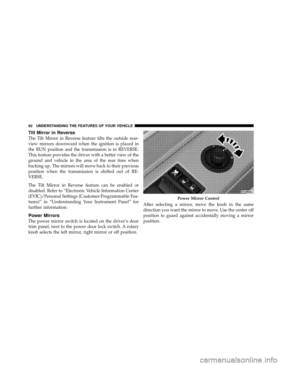
The power mirror switch is located on the driver’s door
trim panel, next to the power door lock switch. A rotary
knob selects the left mirror, right mirror or off position.After selecting a mirror, move the knob in the same
direction you want the mirror to move. Use the center off
position to guard against accidentally moving a mirror
position.
Power Mirror Control
92 UNDERSTANDING THE FEATURES OF YOUR VEHICLE
Page 132 of 465
NOTE:The rear head restraints are not adjustable.
To remove the head restraint, pull upward on the head
restraint to it’s highest position, push in both buttons at
the base of each head restraint rod, and simultaneously
pull up on the head restraint. To install the head restraint, insert the head restraint rods
into each guide, apply pressure down on the headrest
until the head restraint reaches the first lock position,
push the large button in and push down and adjust head
restraint to desired position.
Adjustable Head RestraintsRemoving Head Restraint
3
UNDERSTANDING THE FEATURES OF YOUR VEHICLE 131
Page 136 of 465
WARNING!
•Be certain that the seatback is securely locked into
position. If the seatback is not securely locked into
position, the seat will not provide the proper
stability for child seats and/or passengers. An
improperly latched seat could cause serious injury.
•The cargo area in the rear of the vehicle (with the
rear seatbacks in the locked-up or folded down
position) should not be used as a play area by
children when the vehicle is in motion. They could
be seriously injured in an accident. Children
should be seated and using the proper restraint
system.
DRIVER MEMORY SEAT — IF EQUIPPED
This feature allows the driver to store up to two different
memory profiles for easy recall through a Memory
switch. Each memory profile contains desired position
settings for the driver seat, side mirrors, adjustable
pedals, power tilt, telescopic steering column and a set of
desired radio station presets. Your Remote Keyless Entry
(RKE) transmitter can also be programmed to recall the
same positions when the unlock button is pressed.
3
UNDERSTANDING THE FEATURES OF YOUR VEHICLE 135
Page 138 of 465

1. Adjust all memory profile settings to desired prefer-
ences (i.e., seat, side mirror, adjustable pedals, power tilt,
telescopic steering column, and radio station presets).
2. Press and release the SET button on the Memory
switch, then press the side of the rocker switch labeled (2)
within five seconds. The EVIC will display which
memory position is being set.
NOTE:
•Memory profiles can be set without the vehicle in
PARK, but the vehicle must be in PARK to recall a
memory profile.
•The Recall Memory with Remote Key Unlock feature
can be enabled or disabled. For details, refer to “Elec-
tronic Vehicle Information Center (EVIC)/Customer-
Programmable Features” in “Understanding Your In-
strument Panel” for further information.
Linking and Unlinking the Remote Keyless Entry
Transmitter to Memory
Your RKE transmitters can be programmed to recall one
of two pre-programmed memory profiles by pressing the
UNLOCK button on the RKE transmitter.
To program your RKE transmitters, perform the follow-
ing:
1. Remove the Key Fob from the ignition (or change the
ignition to OFF, for vehicles equipped with Keyless
Go™).
2. Select the desired memory profile 1 or 2.
3. Press and release the SET button on the Memory
switch, then press and release the side of the rocker
switch labeled 1 or 2 accordingly.�Memory Profile Set” (1
or 2) will display in the EVIC.
4. Press and release the LOCK button on the RKE
transmitter within 10 seconds.
3
UNDERSTANDING THE FEATURES OF YOUR VEHICLE 137