2010 CHEVROLET SUBURBAN lights
[x] Cancel search: lightsPage 167 of 608
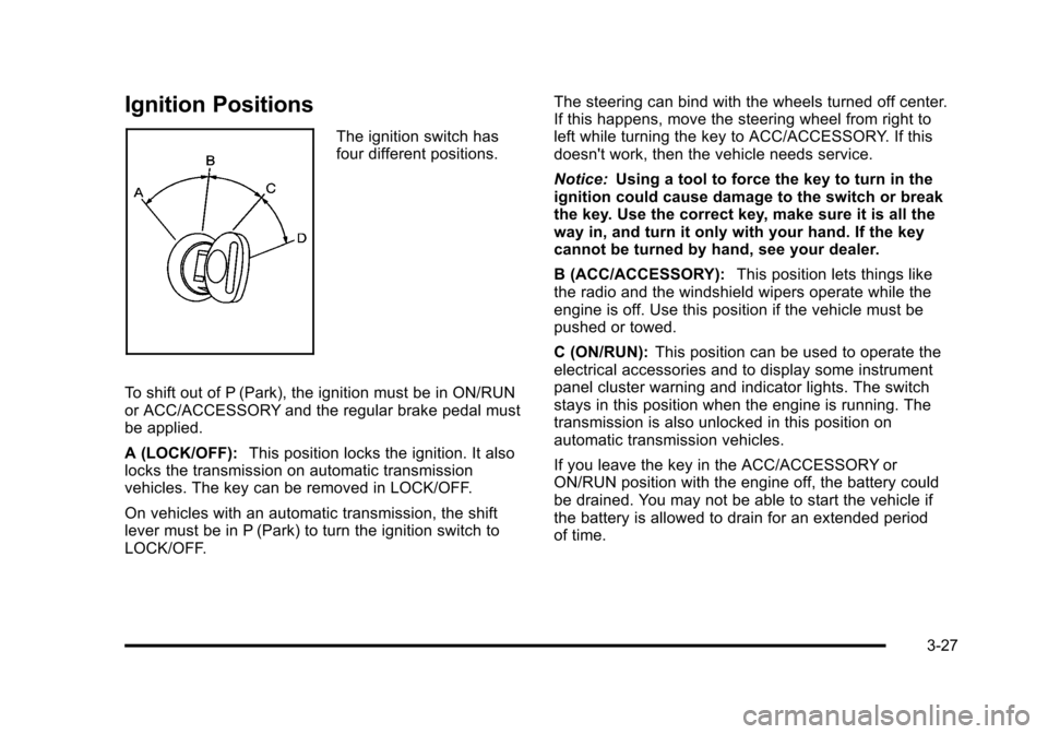
Ignition Positions
The ignition switch has
four different positions.
To shift out of P (Park), the ignition must be in ON/RUN
or ACC/ACCESSORY and the regular brake pedal must
be applied.
A (LOCK/OFF): This position locks the ignition. It also
locks the transmission on automatic transmission
vehicles. The key can be removed in LOCK/OFF.
On vehicles with an automatic transmission, the shift
lever must be in P (Park) to turn the ignition switch to
LOCK/OFF. The steering can bind with the wheels turned off center.
If this happens, move the steering wheel from right to
left while turning the key to ACC/ACCESSORY. If this
doesn't work, then the vehicle needs service.
Notice:
Using a tool to force the key to turn in the
ignition could cause damage to the switch or break
the key. Use the correct key, make sure it is all the
way in, and turn it only with your hand. If the key
cannot be turned by hand, see your dealer.
B (ACC/ACCESSORY): This position lets things like
the radio and the windshield wipers operate while the
engine is off. Use this position if the vehicle must be
pushed or towed.
C (ON/RUN): This position can be used to operate the
electrical accessories and to display some instrument
panel cluster warning and indicator lights. The switch
stays in this position when the engine is running. The
transmission is also unlocked in this position on
automatic transmission vehicles.
If you leave the key in the ACC/ACCESSORY or
ON/RUN position with the engine off, the battery could
be drained. You may not be able to start the vehicle if
the battery is allowed to drain for an extended period
of time.
3-27
Page 180 of 608
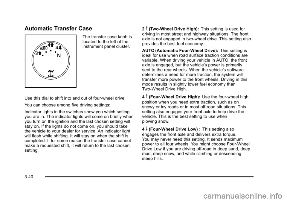
Automatic Transfer Case
The transfer case knob is
located to the left of the
instrument panel cluster.
Use this dial to shift into and out of four-wheel drive.
You can choose among five driving settings:
Indicator lights in the switches show you which setting
you are in. The indicator lights will come on briefly when
you turn on the ignition and the last chosen setting will
stay on. If the lights do not come on, you should take
the vehicle to your dealer for service. An indicator light
will flash while shifting. It will stay on when the shift is
completed. If for some reason the transfer case cannot
make a requested shift, it will return to the last chosen
setting. 2
m(Two-Wheel Drive High):
This setting is used for
driving in most street and highway situations. The front
axle is not engaged in two-wheel drive. This setting also
provides the best fuel economy.
AUTO (Automatic Four-Wheel Drive): This setting is
ideal for use when road surface traction conditions are
variable. When driving your vehicle in AUTO, the front
axle is engaged, but the vehicle's power is primarily
sent to the rear wheels. When the vehicle's software
determines a need for more traction, the system will
transfer more power to the front wheels. Driving in this
mode results in slightly lower fuel economy than
Two-Wheel Drive High.
4
m(Four-Wheel Drive High): Use the four-wheel high
position when you need extra traction, such as on
snowy or icy roads or in most off-road situations. This
setting also engages your front axle to help drive the
vehicle. This is the best setting to use when
plowing snow.
4
n(Four-Wheel Drive Low) : This setting also
engages the front axle and delivers extra torque.
You may never need this setting. It sends maximum
power to all four wheels. You might choose Four-Wheel
Drive Low if you are driving off-road in deep sand, deep
mud, deep snow, and while climbing or descending
steep hills.
3-40
Page 185 of 608
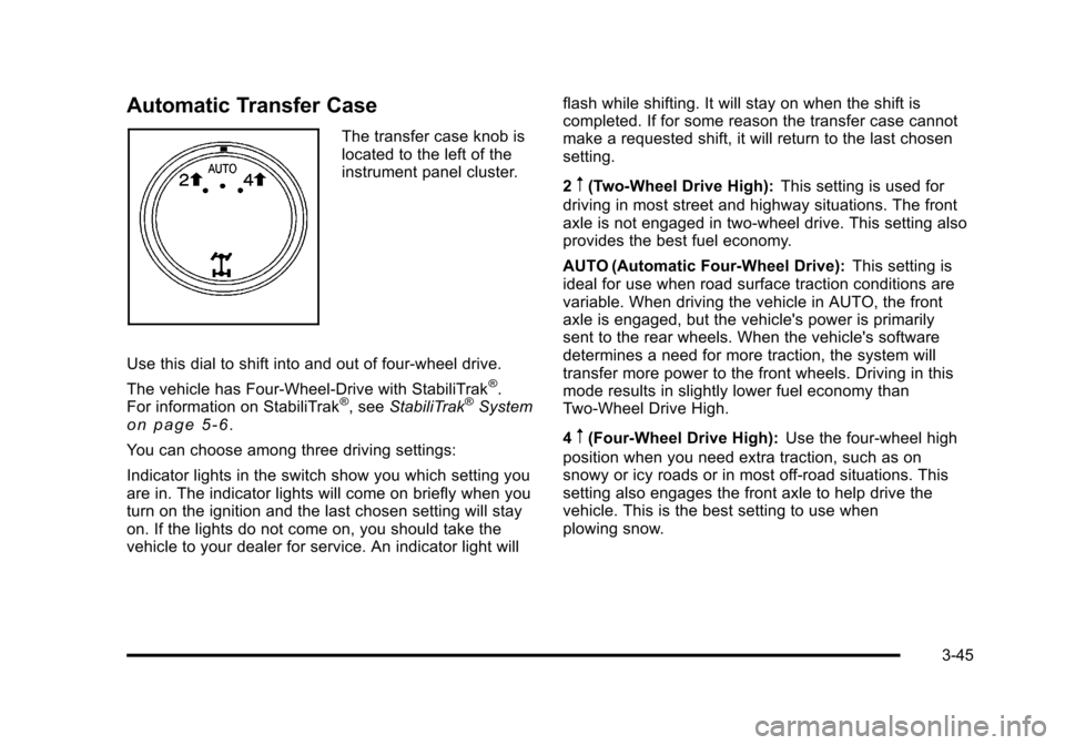
Automatic Transfer Case
The transfer case knob is
located to the left of the
instrument panel cluster.
Use this dial to shift into and out of four-wheel drive.
The vehicle has Four-Wheel-Drive with StabiliTrak
®.
For information on StabiliTrak®, see StabiliTrak®Systemon page 5‑6.
You can choose among three driving settings:
Indicator lights in the switch show you which setting you
are in. The indicator lights will come on briefly when you
turn on the ignition and the last chosen setting will stay
on. If the lights do not come on, you should take the
vehicle to your dealer for service. An indicator light will flash while shifting. It will stay on when the shift is
completed. If for some reason the transfer case cannot
make a requested shift, it will return to the last chosen
setting.
2
m(Two-Wheel Drive High):
This setting is used for
driving in most street and highway situations. The front
axle is not engaged in two-wheel drive. This setting also
provides the best fuel economy.
AUTO (Automatic Four-Wheel Drive): This setting is
ideal for use when road surface traction conditions are
variable. When driving the vehicle in AUTO, the front
axle is engaged, but the vehicle's power is primarily
sent to the rear wheels. When the vehicle's software
determines a need for more traction, the system will
transfer more power to the front wheels. Driving in this
mode results in slightly lower fuel economy than
Two-Wheel Drive High.
4
m(Four-Wheel Drive High): Use the four-wheel high
position when you need extra traction, such as on
snowy or icy roads or in most off-road situations. This
setting also engages the front axle to help drive the
vehicle. This is the best setting to use when
plowing snow.
3-45
Page 205 of 608
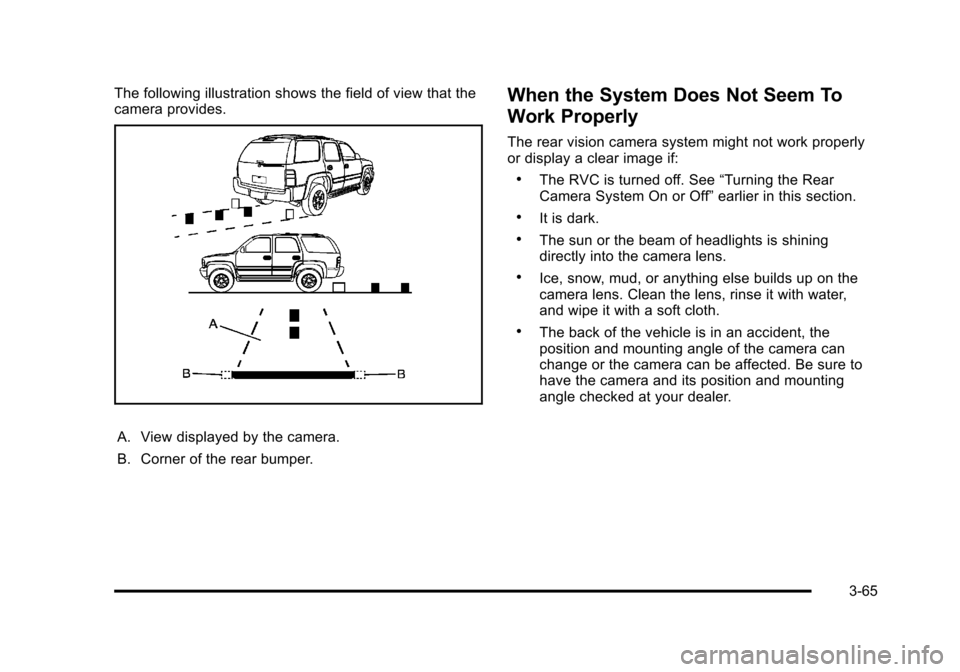
The following illustration shows the field of view that the
camera provides.
A. View displayed by the camera.
B. Corner of the rear bumper.
When the System Does Not Seem To
Work Properly
The rear vision camera system might not work properly
or display a clear image if:
.The RVC is turned off. See“Turning the Rear
Camera System On or Off” earlier in this section.
.It is dark.
.The sun or the beam of headlights is shining
directly into the camera lens.
.Ice, snow, mud, or anything else builds up on the
camera lens. Clean the lens, rinse it with water,
and wipe it with a soft cloth.
.The back of the vehicle is in an accident, the
position and mounting angle of the camera can
change or the camera can be affected. Be sure to
have the camera and its position and mounting
angle checked at your dealer.
3-65
Page 206 of 608
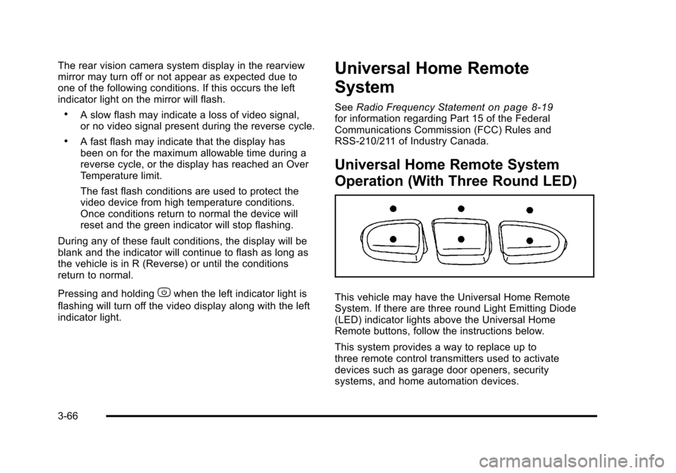
The rear vision camera system display in the rearview
mirror may turn off or not appear as expected due to
one of the following conditions. If this occurs the left
indicator light on the mirror will flash.
.A slow flash may indicate a loss of video signal,
or no video signal present during the reverse cycle.
.A fast flash may indicate that the display has
been on for the maximum allowable time during a
reverse cycle, or the display has reached an Over
Temperature limit.
The fast flash conditions are used to protect the
video device from high temperature conditions.
Once conditions return to normal the device will
reset and the green indicator will stop flashing.
During any of these fault conditions, the display will be
blank and the indicator will continue to flash as long as
the vehicle is in R (Reverse) or until the conditions
return to normal.
Pressing and holding
zwhen the left indicator light is
flashing will turn off the video display along with the left
indicator light.
Universal Home Remote
System
See Radio Frequency Statementon page 8‑19for information regarding Part 15 of the Federal
Communications Commission (FCC) Rules and
RSS-210/211 of Industry Canada.
Universal Home Remote System
Operation (With Three Round LED)
This vehicle may have the Universal Home Remote
System. If there are three round Light Emitting Diode
(LED) indicator lights above the Universal Home
Remote buttons, follow the instructions below.
This system provides a way to replace up to
three remote control transmitters used to activate
devices such as garage door openers, security
systems, and home automation devices.
3-66
Page 211 of 608

2. Write down the eight to 12 switch settings from leftto right as follows:
.When a switch is in the up position, write “Left.”
.When a switch is in the down position, write
“Right.”
.If a switch is set between the up and down
position, write“Middle.”
The switch settings written down in Step 2 now
become the button strokes to be entered into
the Universal Home Remote in Step 4. Be sure
to enter the switch settings written down in
Step 2, in order from left to right, into the
Universal Home Remote, when completing
Step 4.
3. From inside your vehicle, first firmly press all three buttons at the same time for about
three seconds. Release the buttons to put the
Universal Home Remote into programming mode.
4. The indicator lights will blink slowly. Enter eachswitch setting from Step 2 into your vehicle's
Universal Home Remote. You will have two and
one-half minutes to complete Step 4. Now press
one button on the Universal Home Remote for
each switch setting as follows:
.If you wrote “Left,”press the left button in the
vehicle.
.If you wrote “Right,”press the right button in
the vehicle.
.If you wrote “Middle,”press the middle button in
the vehicle.
3-71
Page 212 of 608
5. After entering all of the switch positions, again,firmly press and release all three buttons at the
same time. The indicator lights will turn on.
6. Press and hold the button that will be used to control the garage door until the garage door
moves. The indicator light above the selected
button should slowly blink. This button may need to
be held for up to 55 seconds.
7. Immediately release the button when the garage door moves. The indicator light will blink rapidly
until programming is complete.
8. Press and release the same button again. The garage door should move, confirming that
programming is successful and complete.
To program another Fixed Code device such as an
additional garage door opener, a security device,
or home automation device, repeat Steps 1-8, choosing
a different button in Step 6 than what was used for the
garage door opener.
Using Universal Home Remote
Press and hold the appropriate button for at least half of
a second. The indicator light will come on while the
signal is being transmitted.
Reprogramming Universal Home
Remote Buttons
Any of the three buttons can be reprogrammed by
repeating the instructions.
Erasing Universal Home Remote
Buttons
The programmed buttons should be erased when the
vehicle is sold or the lease ends.
To erase either Rolling Code or Fixed Code on the
Universal Home Remote device: 1. Press and hold the two outside buttons at the same time for approximately 20 seconds, until the
indicator lights, located directly above the buttons,
begin to blink rapidly.
2. Once the indicator lights begin to blink, release both buttons. The codes from all buttons will be
erased.
For help or information on the Universal Home Remote
System, call the customer assistance phone number
under Customer Assistance Offices on page 8‑6.
3-72
Page 219 of 608

Section 4 Instrument Panel
Instrument Panel Overview. . . . . . . . . . . . . . . . . . . . . . . . 4-3
Hazard Warning Flashers . . . . . . . . . . . . . . . . . . . . . . . 4-3
Horn . . . . . . . . . . . . . . . . . . . . . . . . . . . . . . . . . . . . . . . . . . . . 4-3
Tilt Wheel . . . . . . . . . . . . . . . . . . . . . . . . . . . . . . . . . . . . . . . 4-3
Turn Signal/Multifunction Lever . . . . . . . . . . . . . . . . . . 4-4
Turn and Lane-Change Signals . . . . . . . . . . . . . . . . . 4-4
Headlamp High/Low-Beam Changer . . . . . . . . . . . . 4-5
Flash-to-Pass . . . . . . . . . . . . . . . . . . . . . . . . . . . . . . . . . . . 4-5
Windshield Wipers . . . . . . . . . . . . . . . . . . . . . . . . . . . . . . 4-6
Windshield Washer . . . . . . . . . . . . . . . . . . . . . . . . . . . . . 4-6
Rear Window Wiper/Washer . . . . . . . . . . . . . . . . . . . . 4-7
Cruise Control . . . . . . . . . . . . . . . . . . . . . . . . . . . . . . . . . . 4-8
Exterior Lamps . . . . . . . . . . . . . . . . . . . . . . . . . . . . . . . . . 4-11
Headlamps on Reminder . . . . . . . . . . . . . . . . . . . . . . 4-12
Daytime Running Lamps (DRL) . . . . . . . . . . . . . . . . 4-12
Automatic Headlamp System . . . . . . . . . . . . . . . . . . 4-12
Fog Lamps . . . . . . . . . . . . . . . . . . . . . . . . . . . . . . . . . . . . 4-13
Auxiliary Roof-Mounted Lamp . . . . . . . . . . . . . . . . . 4-14
Instrument Panel Brightness . . . . . . . . . . . . . . . . . . . 4-14
Dome Lamps . . . . . . . . . . . . . . . . . . . . . . . . . . . . . . . . . . 4-14
Dome Lamp Override . . . . . . . . . . . . . . . . . . . . . . . . . . 4-15
Entry Lighting . . . . . . . . . . . . . . . . . . . . . . . . . . . . . . . . . . 4-15
Exit Lighting . . . . . . . . . . . . . . . . . . . . . . . . . . . . . . . . . . . 4-15
Reading Lamps . . . . . . . . . . . . . . . . . . . . . . . . . . . . . . . . 4-15
Electric Power Management . . . . . . . . . . . . . . . . . . . 4-15 Battery Run-Down Protection . . . . . . . . . . . . . . . . . . 4-16
Accessory Power Outlet(s) . . . . . . . . . . . . . . . . . . . . . 4-16
Ashtray(s) and Cigarette Lighter . . . . . . . . . . . . . . . 4-17
Climate Controls . . . . . . . . . . . . . . . . . . . . . . . . . . . . . . . . . . 4-18
Climate Control System . . . . . . . . . . . . . . . . . . . . . . . . 4-18
Dual Automatic Climate Control System . . . . . . . 4-20
Outlet Adjustment . . . . . . . . . . . . . . . . . . . . . . . . . . . . . . 4-26
Rear Air Conditioning and Heating System . . . . 4-26
Rear Air Conditioning and Heating System and
Electronic Climate Controls . . . . . . . . . . . . . . . . . . 4-28
Warning Lights, Gauges, and Indicators . . . . . . . . 4-29
Instrument Panel Cluster . . . . . . . . . . . . . . . . . . . . . . . 4-30
Speedometer and Odometer . . . . . . . . . . . . . . . . . . . 4-31
Trip Odometer . . . . . . . . . . . . . . . . . . . . . . . . . . . . . . . . . 4-31
Tachometer . . . . . . . . . . . . . . . . . . . . . . . . . . . . . . . . . . . . 4-31
Safety Belt Reminders . . . . . . . . . . . . . . . . . . . . . . . . . 4-31
Airbag Readiness Light . . . . . . . . . . . . . . . . . . . . . . . . 4-32
Passenger Airbag Status Indicator . . . . . . . . . . . . . 4-33
Charging System Light . . . . . . . . . . . . . . . . . . . . . . . . 4-34
Voltmeter Gauge . . . . . . . . . . . . . . . . . . . . . . . . . . . . . . . 4-35
Brake System Warning Light . . . . . . . . . . . . . . . . . . . 4-36
Antilock Brake System (ABS) Warning Light . . . 4-37
StabiliTrak
®Indicator Light . . . . . . . . . . . . . . . . . . . . . 4-37
Engine Coolant Temperature Gauge . . . . . . . . . . . 4-38
4-1