Page 276 of 626
Transmission Temperature
Press the trip odometer reset stem until TRANS TEMP
displays. This display shows the temperature of the
automatic transmission fluid in either degrees
Fahrenheit (°F) or degrees Celsius (°C).
Trailer Gain and Output
On vehicles with the Integrated Trailer Brake Control
(ITBC) system, the trailer brake display appears in the
DIC. Press the trip odometer reset stem until TRAILER
GAIN and OUTPUT display.
TRAILER GAIN shows the trailer gain setting. This
setting can be adjusted from 0.0 to 10.0 with either a
trailer connected or disconnected. To adjust this setting,
see“Integrated Trailer Brake Control System” under
Towing a Trailer
on page 5‑51for more information.
OUTPUT shows the power output to the trailer anytime
a trailer with electric brakes is connected. Output is
displayed in 0 to 10 bars. Dashes may appear in the
OUTPUT display. See “Integrated Trailer Brake Control
System” underTowing a Trailer
on page 5‑51for more
information.
Compass Zone Setting
This display allows for setting the compass zone. See
DIC Compasson page 4‑60for more information.
Compass Recalibration
This display allows for calibrating the compass. See
DIC Compasson page 4‑60for more information.
Oil Life
To access this display, the vehicle must be in P (Park).
Press the trip odometer reset stem until OIL LIFE
REMAINING displays. This display shows an estimate
of the oil's remaining useful life. If you see 99% OIL
LIFE REMAINING on the display, that means 99% of
the current oil life remains. The engine oil life system
will alert you to change the oil on a schedule consistent
with your driving conditions.
When the remaining oil life is low, the CHANGE
ENGINE OIL SOON message will appear on the
display. See “CHANGE ENGINE OIL SOON” underDIC
Warnings and Messages
on page 4‑63. You should
change the oil as soon as you can. See Engine Oilon
page 6‑18. In addition to the engine oil life system
monitoring the oil life, additional maintenance is
recommended in the Maintenance Schedule in this
manual. See Scheduled Maintenance
on page 7‑3for
more information.
4-58
Page 374 of 626
In this mode, engine power is not reduced automatically
and the driven wheels can spin more freely. This can
cause the brake-traction control to activate constantly.
Notice:If the wheel(s) of one axle is allowed to spin
excessively while the StabiliTrak, ABS and brake
warning lights and any relevant DIC messages are
displayed, the transfer case could be damaged. The
repairs would not be covered by the vehicle
warranty. Reduce engine power and do not spin the
wheel(s) excessively while these lights and
messages are displayed.
The traction control system may activate on dry or
rough roads or under conditions such as heavy
acceleration while turning or abrupt upshifts/downshifts
of the transmission. When this happens, a reduction in
acceleration may be noticed, or a noise or vibration may
be heard. This is normal.
If cruise control is being used when the system
activates, the StabiliTrak light will flash and cruise
control will automatically disengage. Cruise control may
be reengaged when road conditions allow. See Cruise
Control on page 4‑7.
StabiliTrak may also turn off automatically if it
determines that a problem exists with the system. If the
problem does not clear itself after restarting the vehicle,
see your dealer for service.Locking Rear Axle
Vehicles with a locking rear axle can give more traction
on snow, mud, ice, sand or gravel. It works like a
standard axle most of the time, but when traction is low,
this feature will allow the rear wheel with the most
traction to move the vehicle.
Steering
Power Steering
If the vehicle is a Two‐mode Hybrid, see the Two‐mode
Hybrid manual for more information.
If power steering assist is lost because the engine stops
or the system is not functioning, the vehicle can be
steered but it will take more effort.
Steering Tips
It is important to take curves at a reasonable speed.
Traction in a curve depends on the condition of the tires
and the road surface, the angle at which the curve is
banked, and vehicle speed. While in a curve, speed is
the one factor that can be controlled.
If there is a need to reduce speed, do it before entering
the curve, while the front wheels are straight.
5-8
Page 441 of 626
Leaving After Parking on a Hill
1. Apply and hold the brake pedal.
2. Start the engine
3. Shift into a gear
4. Release the parking brake
5. Let up on the brake pedal.
6. Drive slowly until the trailer is clear of the chocks.
7. Stop and have someone pick up and store thechocks.
Maintenance When Trailer Towing
The vehicle needs service more often when pulling a
trailer. See this manual's Maintenance Schedule or
Index for more information. Things that are especially
important in trailer operation are automatic transmission
fluid, engine oil, axle lubricant, belts, cooling system
and brake system. It is a good idea to inspect these
before and during the trip.
Check periodically to see that all hitch nuts and bolts
are tight.
Trailer Wiring Harness
The vehicle is equipped with one of the following wiring
harnesses for towing a trailer or hauling a slide-in
camper.
Basic Trailer Wiring
All regular, extended cab and crew cab pickups have a
seven‐wire trailer towing harness.
For vehicles not equipped with heavy duty trailering, the
harness is secured to the vehicle's frame behind the
spare tire mount. The harness requires the installation
of a trailer connector, which is available through your
dealer.
If towing a light‐duty trailer with a standard four‐way
round pin connector, an adapter is available from your
dealer.
5-75
Page 460 of 626
Engine Compartment Overview
If the vehicle has a diesel engine and/or an Allison Transmission, see the DURAMAX®Diesel manual.
5.3 L V8 Engine (4.3 L V6 Engine, 4.8 L V6 Engine, 6.0 L V8 Engine and 6.2 L V8 Engine similar):
6-16
Page 473 of 626
3. Install the dipstick by pushing it back in all the way,wait three seconds, and then pull it back out again.
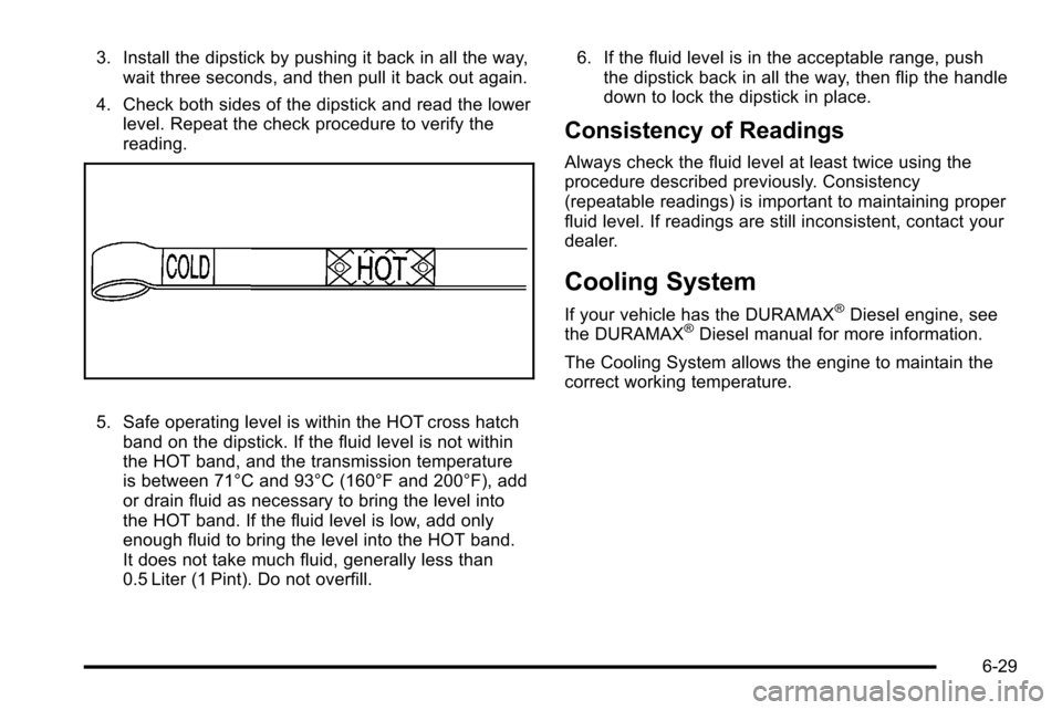
4. Check both sides of the dipstick and read the lower level. Repeat the check procedure to verify the
reading.
5. Safe operating level is within the HOT cross hatchband on the dipstick. If the fluid level is not within
the HOT band, and the transmission temperature
is between 71°C and 93°C (160°F and 200°F), add
or drain fluid as necessary to bring the level into
the HOT band. If the fluid level is low, add only
enough fluid to bring the level into the HOT band.
It does not take much fluid, generally less than
0.5 Liter (1 Pint). Do not overfill. 6. If the fluid level is in the acceptable range, push
the dipstick back in all the way, then flip the handle
down to lock the dipstick in place.
Consistency of Readings
Always check the fluid level at least twice using the
procedure described previously. Consistency
(repeatable readings) is important to maintaining proper
fluid level. If readings are still inconsistent, contact your
dealer.
Cooling System
If your vehicle has the DURAMAX®Diesel engine, see
the DURAMAX®Diesel manual for more information.
The Cooling System allows the engine to maintain the
correct working temperature.
6-29
Page 489 of 626
To avoid the possibility of the vehicles rolling, set
the parking brake firmly on both vehicles involved
in the jump start procedure. Put the automatic
transmission in P (Park) or a manual transmission
in Neutral before setting the parking brake. If you
have a four-wheel-drive vehicle, be sure the
transfer case is in a drive gear, not in Neutral.
Notice: If you leave the radio or other accessories
on during the jump starting procedure, they could
be damaged. The repairs would not be covered by
the warranty. Always turn off the radio and other
accessories when jump starting the vehicle.
4. Turn off the ignition on both vehicles. Unplug unnecessary accessories plugged into the
cigarette lighter or the accessory power outlets.
Turn off the radio and all the lamps that are not
needed. This will avoid sparks and help save both
batteries. And it could save the radio!
5. Open the hood on the other vehicle and locate the positive (+) and negative (−) terminal locations on
that vehicle.
The positive (+) terminal, is located under a red
plastic cover at the positive battery post. To
uncover the positive (+) terminal, open the red
plastic cover.
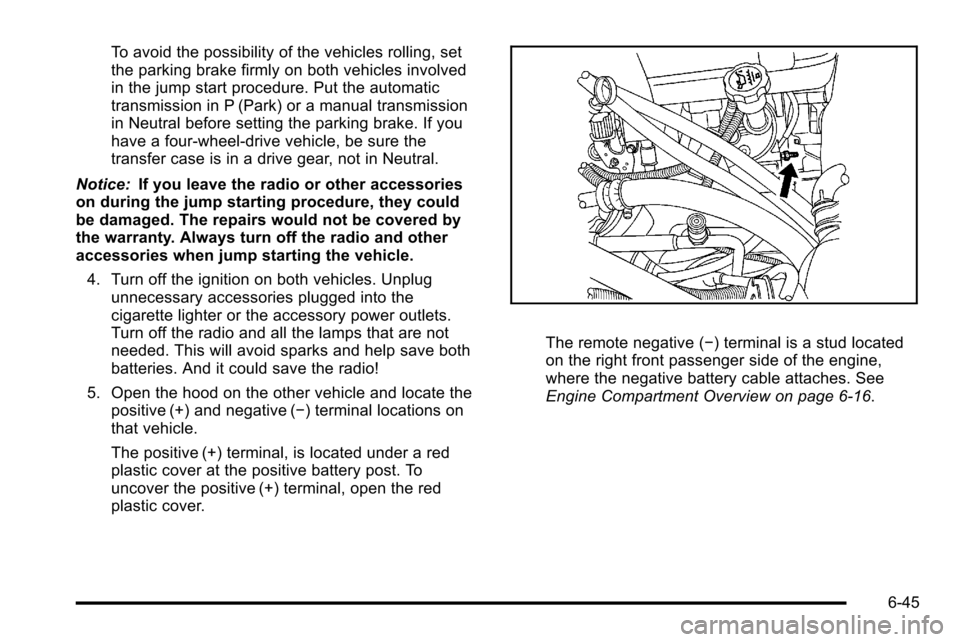
The remote negative (−) terminal is a stud located
on the right front passenger side of the engine,
where the negative battery cable attaches. See
Engine Compartment Overview on page 6‑16.
6-45
Page 534 of 626
A rear blowout, particularly on a curve, acts much like a
skid and may require the same correction you would
use in a skid. In any rear blowout remove your foot from
the accelerator pedal. Get the vehicle under control by
steering the way you want the vehicle to go. It may be
very bumpy and noisy, but you can still steer. Gently
brake to a stop, well off the road if possible.
{WARNING:
Lifting a vehicle and getting under it to do
maintenance or repairs is dangerous without the
appropriate safety equipment and training. If a
jack is provided with the vehicle, it is designed
only for changing a flat tire. If it is used for
anything else, you or others could be badly
injured or killed if the vehicle slips off the jack. If a
jack is provided with the vehicle, only use it for
changing a flat tire.
If a tire goes flat, the next part shows how to use the
jacking equipment to change a flat tire safely.
Changing a Flat Tire
If a tire goes flat, avoid further tire and wheel damage
by driving slowly to a level place. Turn on the hazard
warning flashers. See Hazard Warning Flashers
on
page 4‑3.
{WARNING:
Changing a tire can be dangerous. The vehicle
can slip off the jack and roll over or fall on you or
other people. You and they could be badly injured
or even killed. Find a level place to change your
tire. To help prevent the vehicle from moving:
1. Set the parking brake firmly.
2. Put an automatic transmission shift lever in P (Park), or shift a manual transmission to
1 (First) or R (Reverse).
(Continued)
6-90
Page 571 of 626
ApplicationCapacities
English Metric
Fuel Tank
1500 Series Standard and Short Box 26.0 gal 98.0 L
1500 Series Long Box 34.0 gal 128.7 L
2500 Series Standard Box 26.0 gal 98.0 L
2500 Series and 3500 Series Long Box 34.0 gal 128.7 L
3500 Series Chassis Cab 50.0 gal 189.0 L
3500 Chassis Cab –Front Tank 27.0 gal 102.0 L
3500 Chassis Cab –Rear Tank (if equipped) 23.0 gal 87.0 L
Transmission Fluid (Pan Removal and Filter Replacement) Auto 4-Speed Transmission 4L60-E Electronic Transmission 5.0 qt 4.7 L
Auto 6-Speed Transmission 6L80-E 6.0 qt 5.7 L
Auto 6-Speed Transmission 6L90-E 6.3 qt 6.0 L
Auto 6-Speed Transmission Allison 7.4 qt 7.0 L
Transfer Case Fluid 1.6 qt 1.5 L
Wheel Nut Torque 140 ft lb 190 Y
All capacities are approximate. When adding, be sure to fill to the approximate level, as recommended in this manual.
Recheck fluid level after filling.
6-127