2010 Alfa Romeo Brera/Spider instrument panel
[x] Cancel search: instrument panelPage 111 of 271
109
SAFETY
DEVICES
WARNING
LIGHTS AND
MESSAGES
IN AN
EMERGENCY
CAR
MAINTENANCE
TECHNICAL
SPECIFICATIONS
INDEX
DASHBOARD
AND
CONTROLS
CORRECT USE
OF THE CAR
TYRE PRESSURE MONITORING SYSTEM -
T.P.M.S. (where provided)
(for versions/markets, where provided)
The car can be equipped with the
T.P.M.S. (Tyre Pressure Monitoring Sys-
tem). This system consists of a radio-fre-
quency sensor, installed on each wheel
(on the rim inside the tyre) that sends
pressure information to the control unit.
IMPORTANT NOTES
Failure indications will not be stored and
therefore will not be displayed when
turning the engine off and on again. If
failure persists, the control unit will send
warning indications to the instrument
panel only after a few seconds when the
car is moving.
Tyre pressure should be checked with
tyres cold. Should it become necessary
for whatever reason to check pressure
with hot tyres, do not reduce pressure
although it is higher than the prescribed
value but repeat the check when tyres
are cold (see section “Wheels” in sec-
tion “Technical Specifications”).T.P.M.S. cannot indicate sudden tyre
pressure drops (e.g.: tyre burst). In this
event, brake the car cautiously and
avoid sudden steering.
The T.P.M.S. system requires special
equipment. Consult Alfa Romeo Autho-
rized Services to know what type of ac-
cessories are compatible with the sys-
tem (wheels, wheel caps, etc.). Using
other accessories could cause system
malfunctioning. Due to inflation valve
special characteristics, use only tyre re-
pair sealants approved by Alfa Romeo;
other sealants could cause system mal-
functioning.
The T.P.M.S. does not
exempt the driver from
checking tyre pressure, includ-
ing the space-saver spare
wheel (for versions/markets,
where provided) at regular in-
tervals.
WARNING
Page 142 of 271
140
SAFETY
DEVICES
WARNING
LIGHTS AND
MESSAGES
IN AN
EMERGENCY
CAR
MAINTENANCE
TECHNICAL
SPECIFICATIONS
INDEX
DASHBOARD
AND
CONTROLS
CORRECT USE
OF THE CAR
WARNINGS
If at start-up the engine turns off, restart
it by pressing the clutch or brake pedal
and then press button START/STOP.
If after a few attempts the engine does
not start, do not insist but contact Alfa
Romeo Authorized Services.
With car started the electronic key is
locked into the ignition device and it can
be removed only after switching the en-
gine off. With car running and key locked
into the ignition device, forced key re-
moval could damage the ignition device. The starter automatically operates until
the engine starts.
With engine off and electronic key in-
serted in the ignition device, it is possi-
ble to operate the automatic ignition
briefly pressing the START/STOPbut-
ton and keeping the clutch pedal
pressed.
In the event of cold weather, we rec-
ommend to wait for warning light
m
turn off before operating the starter.
IMPORTANTIt is possible to start the
engine keeping pressed only the brake
pedal. In that case, automatic start is not
enabled. Then press the START/STOP
button and release it as soon as the en-
gine starts.Start-up failures, if any, are indicated by
the turning on of the warning light
Yon
the instrument panel (on certain versions
a dedicated message is displayed). In this
case contact Alfa Romeo Authorized Ser-
vices.
If the engine will not start after pressing
buttonSTART/STOPrepeat the start-
up procedure by pressing the other pedal
(clutch or brake).
Page 143 of 271

141
SAFETY
DEVICES
WARNING
LIGHTS AND
MESSAGES
IN AN
EMERGENCY
CAR
MAINTENANCE
TECHNICAL
SPECIFICATIONS
INDEX
DASHBOARD
AND
CONTROLS
CORRECT USE
OF THE CAR
Start-up failures
The system can recognise start-up fail-
ures.
In the event of failure, the electronic key
can be removed from the ignition device to
enable the driver to carry out the follow-
ing operations:
❒turn the instrument panel off by
pressing button START/STOPor
removing the electronic key from the
ignition device;
❒start the engine again by pressing the
clutch/brake pedal and button
START/STOP.
IMPORTANT With engine raced while
the car is running, due to safety reasons
it is not possible to remove the electronic
key from the ignition device. To remove
it, press buttonSTART/STOPwith
brake pedal (or clutch pedal) released and
car stopped.
HOW TO WARM UP THE
ENGINE AFTER IT HAS JUST
STARTED (petrol and diesel
engines)
Proceed as follows:
❒Drive off slowly, letting the engine
turn at medium revs. Do not accel-
erate abruptly;
❒Do not drive at full performance for
the initial kilometres. Wait until the
coolant temperature gauge starts
moving.
STOPPING THE ENGINE
With car stopped press button
START/STOP. When the engine is off
it will be possible to remove the electronic
key from the ignition device.
In an emergency and
also for safety rea-
sons, it is possible to kill the
engine while the car is running
by pressing repeatedly (three
times in 2 seconds) or keeping
pressed the START/STOP but-
ton for a few seconds. In this
case the power steering is no
longer available.
WARNING
Page 144 of 271

142
SAFETY
DEVICES
WARNING
LIGHTS AND
MESSAGES
IN AN
EMERGENCY
CAR
MAINTENANCE
TECHNICAL
SPECIFICATIONS
INDEX
DASHBOARD
AND
CONTROLS
CORRECT USE
OF THE CAR
A quick burst on the ac-
celerator before turning
off the engine serves
absolutely no practical purpose,
it wastes fuel and is damaging
especially to turbocharged en-
gines.
IMPORTANTAfter a taxing drive, you
should allow the engine to “catch its
breath” before turning it off by letting it
idle to allow the temperature in the en-
gine compartment to fall.
IMPORTANTTurning the car off will
deactivate the electronic safety systems
and turn off the external lights.
IMPORTANTKilling the engine while
the car is running, due to safety reasons,
it will not be possible to take the elec-
tronic key out of the ignition device. To
remove it, turn the instrument panel on
and off by pressing button
START/STOPwith brake pedal (or
clutch pedal) released and car stopped.
REMOVING THE
ELECTRONIC KEY FROM THE
IGNITION DEVICE IN AN
EMERGENCY
In the event of a failure at engine switch-
ing off system or at electronic key un-
locking system proceed as follows:
❒press the unlocking button to remove
the metal insert (see paragraph
“Electronic key” in section “Dash-
board and controls”);
❒fit the metal insert B-fig. 1of the
electronic key into the slot A;
❒remove the electronic key from the
ignition device.
A0F0043mfig. 1
IMPORTANTOnly fit the metal insert
B-fig.1of the electronic key into slot A.
IMPORTANTIf emergency removal
is carried out with the engine running,
the engine and the instrument panel will
be turned off and the steering lock will
not be engaged; always stop the car be-
fore emergency removal.
Page 145 of 271
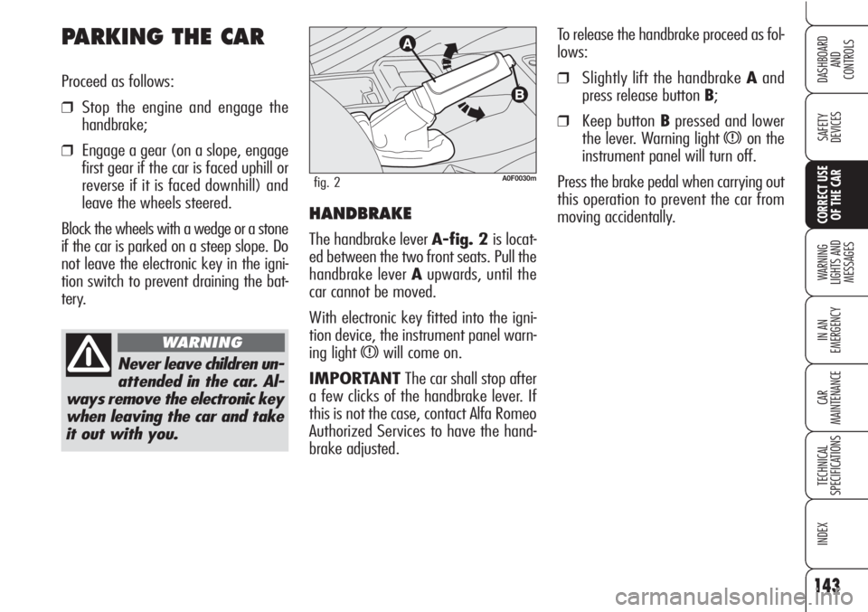
To release the handbrake proceed as fol-
lows:
❒Slightly lift the handbrake Aand
press release button B;
❒Keep button Bpressed and lower
the lever. Warning light
xon the
instrument panel will turn off.
Press the brake pedal when carrying out
this operation to prevent the car from
moving accidentally.
HANDBRAKE
The handbrake lever A-fig. 2 is locat-
ed between the two front seats. Pull the
handbrake lever Aupwards, until the
car cannot be moved.
With electronic key fitted into the igni-
tion device, the instrument panel warn-
ing light
xwill come on.
IMPORTANT The car shall stop after
a few clicks of the handbrake lever. If
this is not the case, contact Alfa Romeo
Authorized Services to have the hand-
brake adjusted.
A0F0030mfig. 2
PARKING THE CAR
Proceed as follows:
❒Stop the engine and engage the
handbrake;
❒Engage a gear (on a slope, engage
first gear if the car is faced uphill or
reverse if it is faced downhill) and
leave the wheels steered.
Block the wheels with a wedge or a stone
if the car is parked on a steep slope. Do
not leave the electronic key in the igni-
tion switch to prevent draining the bat-
tery.
Never leave children un-
attended in the car. Al-
ways remove the electronic key
when leaving the car and take
it out with you.
WARNING
143
SAFETY
DEVICES
WARNING
LIGHTS AND
MESSAGES
IN AN
EMERGENCY
CAR
MAINTENANCE
TECHNICAL
SPECIFICATIONS
INDEX
DASHBOARD
AND
CONTROLS
CORRECT USE
OF THE CAR
Page 178 of 271

176
SAFETY
DEVICES
WARNING
LIGHTS AND
MESSAGES
IN AN
EMERGENCY
CAR
MAINTENANCE
TECHNICAL
SPECIFICATIONS
INDEX
DASHBOARD
AND
CONTROLS
CORRECT USE
OF THE CAR
When you have finished:
❒Stow the spare wheel in the space
provided in the boot;
❒Fit the jack partially open in its con-
tainer forcing it lightly to prevent it
from vibrating when travelling;
❒Put the tools back into their places
in the container;
❒Arrange the container complete with
tools on the space-saver spare
wheel;
❒Reposition properly the boot stiff cov-
ering.
A0F0114mfig. 11
QUICK TYRE REPAIR
KIT FIX&GO
automatic
The car is provided with the quick tyre
repair kit “FIX&GO automatic”, instead
of the traditional tool kit and space-saver
spare wheel.
The kit fig. 11is placed in the boot. In
the kit container you will also find the
screwdriver and the tow hitch. The quick tyre repair kit includes:
❒a bottle A-fig. 11containing the
sealer, fitted with:
- filling pipe B
- sticker Cbearing the notice “max.
80 km/h”, to be placed in a po-
sition visible to the driver (on the
instrument panel) after fixing the
tyre;
❒compressorDwith pressure gauge
and fittings;
Page 201 of 271

199
SAFETY
DEVICES
WARNING
LIGHTS AND
MESSAGES
IN AN
EMERGENCY
CAR
MAINTENANCE
TECHNICAL
SPECIFICATIONS
INDEX
DASHBOARD
AND
CONTROLS
CORRECT USE
OF THE CAR
FUSE SUMMARY TABLE
LIGHTS FUSE AMPERE FIGURE
Right main beam headlight F14 10 52
Left main beam headlight F15 10 52
Right dipped beam headlight F12 15 48
Left dipped beam headlight F13 15 48
Front fog light F30 15 52
Reversing light F35 7.5 48
Third brake light F37 10 48
Front/rear ceiling light F39 10 48
Front ceiling light F49 7.5 48
Direction indicators F53 10 48
Hazard lights F53 10 48
USERS FUSE AMPERE FIGURE
Engine compartment control unit F70 (MEGA-FUSE) 150 50
Instrument panel control unit F71 70 50
Fuel pre-heating unit (diesel versions) F73 60 50
Boot control unit F01 (MAXI-FUSE) 70 52
Instrument panel control unit F01 (MAXI-FUSE) 70 52
Page 203 of 271

201
SAFETY
DEVICES
WARNING
LIGHTS AND
MESSAGES
IN AN
EMERGENCY
CAR
MAINTENANCE
TECHNICAL
SPECIFICATIONS
INDEX
DASHBOARD
AND
CONTROLS
CORRECT USE
OF THE CAR
USERS FUSE AMPERE FIGURE
Water in diesel fuel filter sensor/flow meter F35 7.5 48
Brake light switch/central console control panel F35 7.5 48
Cruise Control F35 7.5 48
AQS sensor F35 7.5 48
Disponible F36 – 48
Instrument panel branch point F37 10 48
Front headlight control unit/Power to control unit
for gas-discharge headights (Bixenon) (where provided) F37 10 48
Boot locking/unlocking gearmotor F38 15 48
EOBD system diagnostic socket F39 10 48
T.P.M.S. control unit F39 10 48
Mobile phone presetting F39 10 48
Alarm system control unit (for versions/markets, where provided) F39 10 48
Climate control system F39 10 48
Heated rear window F40 30 48
Windscreen washer/rear window washer nozzle demister F41 7.5 48
Heated mirror demister F41 7.5 48
Brake branch point power (ABS/VDC) –
Steering angle branch point – Yawing sensor F42 7.5 48
Windscreen wiper/washer F43 30 48