Page 35 of 190
2-13
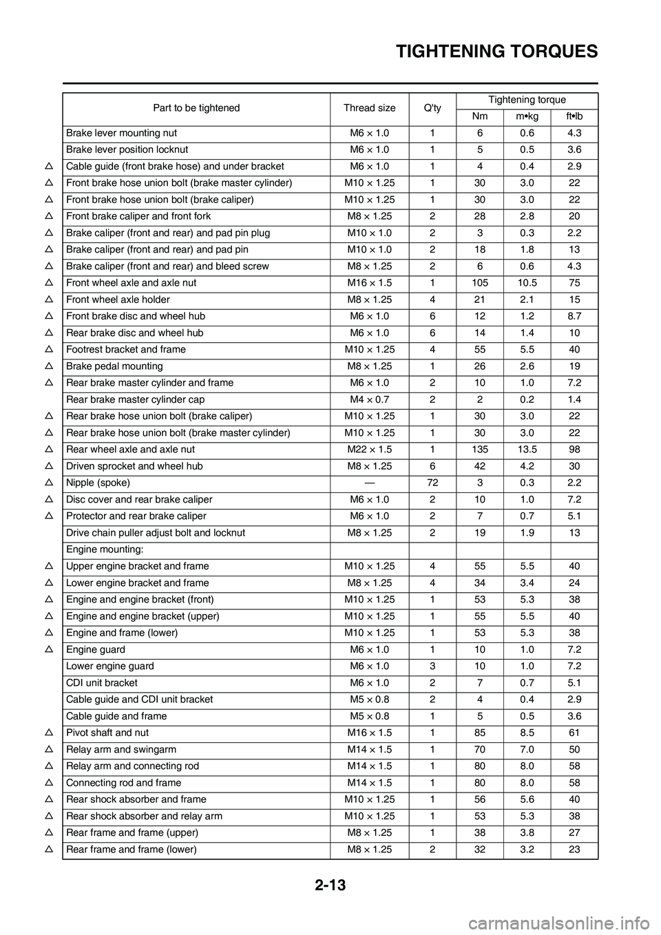
TIGHTENING TORQUES
Brake lever mounting nut M6 × 1.0 1 6 0.6 4.3
Brake lever position locknut M6 × 1.0 1 5 0.5 3.6
△Cable guide (front brake hose) and under bracket M6 × 1.0 1 4 0.4 2.9
△Front brake hose union bolt (brake master cylinder) M10 × 1.25 1 30 3.0 22
△Front brake hose union bolt (brake caliper) M10 × 1.25 1 30 3.0 22
△Front brake caliper and front fork M8 × 1.25 2 28 2.8 20
△Brake caliper (front and rear) and pad pin plug M10 × 1.0 2 3 0.3 2.2
△Brake caliper (front and rear) and pad pin M10 × 1.0 2 18 1.8 13
△Brake caliper (front and rear) and bleed screw M8 × 1.25 2 6 0.6 4.3
△Front wheel axle and axle nut M16 × 1.5 1 105 10.5 75
△Front wheel axle holder M8 × 1.25 4 21 2.1 15
△Front brake disc and wheel hub M6 × 1.0 6 12 1.2 8.7
△Rear brake disc and wheel hub M6 × 1.0 6 14 1.4 10
△Footrest bracket and frame M10 × 1.25 4 55 5.5 40
△Brake pedal mounting M8 × 1.25 1 26 2.6 19
△Rear brake master cylinder and frame M6 × 1.0 2 10 1.0 7.2
Rear brake master cylinder cap M4 × 0.7 2 2 0.2 1.4
△Rear brake hose union bolt (brake caliper) M10 × 1.25 1 30 3.0 22
△Rear brake hose union bolt (brake master cylinder) M10 × 1.25 1 30 3.0 22
△Rear wheel axle and axle nut M22 × 1.5 1 135 13.5 98
△Driven sprocket and wheel hub M8 × 1.25 6 42 4.2 30
△Nipple (spoke) — 72 3 0.3 2.2
△Disc cover and rear brake caliper M6 × 1.0 2 10 1.0 7.2
△Protector and rear brake caliper M6 × 1.0 2 7 0.7 5.1
Drive chain puller adjust bolt and locknut M8 × 1.25 2 19 1.9 13
Engine mounting:
△Upper engine bracket and frame M10 × 1.25 4 55 5.5 40
△Lower engine bracket and frame M8 × 1.25 4 34 3.4 24
△Engine and engine bracket (front) M10 × 1.25 1 53 5.3 38
△Engine and engine bracket (upper) M10 × 1.25 1 55 5.5 40
△Engine and frame (lower) M10 × 1.25 1 53 5.3 38
△Engine guard M6 × 1.0 1 10 1.0 7.2
Lower engine guard M6 × 1.0 3 10 1.0 7.2
CDI unit bracket M6 × 1.0 2 7 0.7 5.1
Cable guide and CDI unit bracket M5 × 0.8 2 4 0.4 2.9
Cable guide and frame M5 × 0.8 1 5 0.5 3.6
△Pivot shaft and nut M16 × 1.5 1 85 8.5 61
△Relay arm and swingarm M14 × 1.5 1 70 7.0 50
△Relay arm and connecting rod M14 × 1.5 1 80 8.0 58
△Connecting rod and frame M14 × 1.5 1 80 8.0 58
△Rear shock absorber and frame M10 × 1.25 1 56 5.6 40
△Rear shock absorber and relay arm M10 × 1.25 1 53 5.3 38
△Rear frame and frame (upper) M8 × 1.25 1 38 3.8 27
△Rear frame and frame (lower) M8 × 1.25 2 32 3.2 23Part to be tightened Thread size Q'tyTightening torque
Nm m•kg ft•lb
Page 37 of 190
2-15
TIGHTENING TORQUES
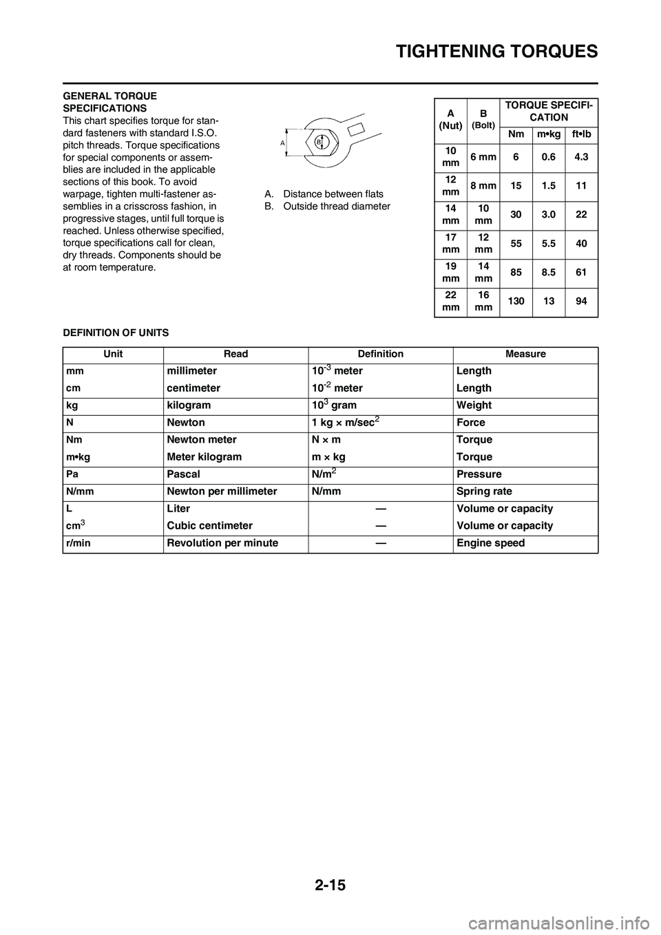
GENERAL TORQUE
SPECIFICATIONS
This chart specifies torque for stan-
dard fasteners with standard I.S.O.
pitch threads. Torque specifications
for special components or assem-
blies are included in the applicable
sections of this book. To avoid
warpage, tighten multi-fastener as-
semblies in a crisscross fashion, in
progressive stages, until full torque is
reached. Unless otherwise specified,
torque specifications call for clean,
dry threads. Components should be
at room temperature.A. Distance between flats
B. Outside thread diameter
DEFINITION OF UNITS
A
(Nut)B
(Bolt)TORQUE SPECIFI-
CATION
Nm m•kg ft•lb
10
mm6 mm 6 0.6 4.3
12
mm8 mm 15 1.5 11
14
mm10
mm30 3.0 22
17
mm12
mm55 5.5 40
19
mm14
mm85 8.5 61
22
mm16
mm130 13 94
Unit Read Definition Measure
mm
millimeter 10-3 meter Length
cmcentimeter 10-2 meter Length
kgkilogram 103 gram Weight
NNewton 1 kg × m/sec2Force
NmNewton meter N × m Torque
m•kgMeter kilogram m × kg Torque
PaPascal N/m2Pressure
N/mmNewton per millimeter N/mm Spring rate
LLiter — Volume or capacity
cm3Cubic centimeter — Volume or capacity
r/minRevolution per minute — Engine speed
Page 42 of 190
2-20
CABLE ROUTING DIAGRAM
1. Hot starter cable
2. Clamp
3. Throttle position sensor lead
4. Hump (frame)
5. Neutral switch lead
6. Engine bracket
7. Lower engine guard stay
8. CDI magneto lead
9. Clutch cable
10. Radiator breather hose
11. Radiator hose 212. Engine stop switch lead
13. Sub-wire harness
14. Ground lead
15. CDI unit bracket
16. CDI unit
17. Cable guide
18. Ignition coil lead
19. Throttle cable
20. Hot starter cable protector
21. Rubber capA. Fasten the hot starter cable and
throttle cables onto the frame.
B. Fasten the hot starter cable,
throttle cables, throttle position
sensor lead and ignition coil lead
to the frame.
C. Pass the throttle position sensor
lead over the hot starter cable.
D. Pass the neutral switch lead on
the inside of the engine bracket.
Page 43 of 190
2-21
CABLE ROUTING DIAGRAM
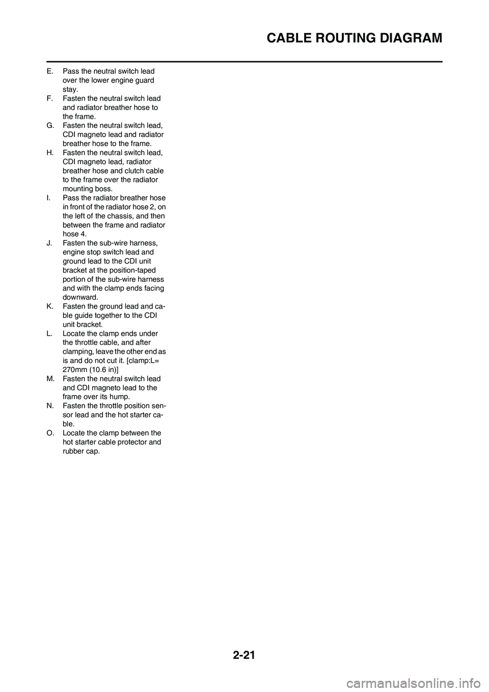
E. Pass the neutral switch lead
over the lower engine guard
stay.
F. Fasten the neutral switch lead
and radiator breather hose to
the frame.
G. Fasten the neutral switch lead,
CDI magneto lead and radiator
breather hose to the frame.
H. Fasten the neutral switch lead,
CDI magneto lead, radiator
breather hose and clutch cable
to the frame over the radiator
mounting boss.
I. Pass the radiator breather hose
in front of the radiator hose 2, on
the left of the chassis, and then
between the frame and radiator
hose 4.
J. Fasten the sub-wire harness,
engine stop switch lead and
ground lead to the CDI unit
bracket at the position-taped
portion of the sub-wire harness
and with the clamp ends facing
downward.
K. Fasten the ground lead and ca-
ble guide together to the CDI
unit bracket.
L. Locate the clamp ends under
the throttle cable, and after
clamping, leave the other end as
is and do not cut it. [clamp:L=
270mm (10.6 in)]
M. Fasten the neutral switch lead
and CDI magneto lead to the
frame over its hump.
N. Fasten the throttle position sen-
sor lead and the hot starter ca-
ble.
O. Locate the clamp between the
hot starter cable protector and
rubber cap.
Page 46 of 190
2-24
CABLE ROUTING DIAGRAM
1. Throttle cable
2. Clamp
3. Hot starter cable
4. Clutch cable
5. Engine stop switch lead
6. Cable guide
7. Brake hose
8. Hose guide
A. Fasten the engine stop switch
lead to the handlebar.B. Pass the clutch cable and hot
starter cable through the cable
guide.
C. Pass the brake hose in front of
the number plate.
D. Pass the throttle cables through
the cable guide.
E. Pass the clutch cable and hot
starter cable through the cable
guide on the number plate.
Page 47 of 190
3-1
MAINTENANCE INTERVALS
REGULAR INSPECTION AND ADJUSTMENTS
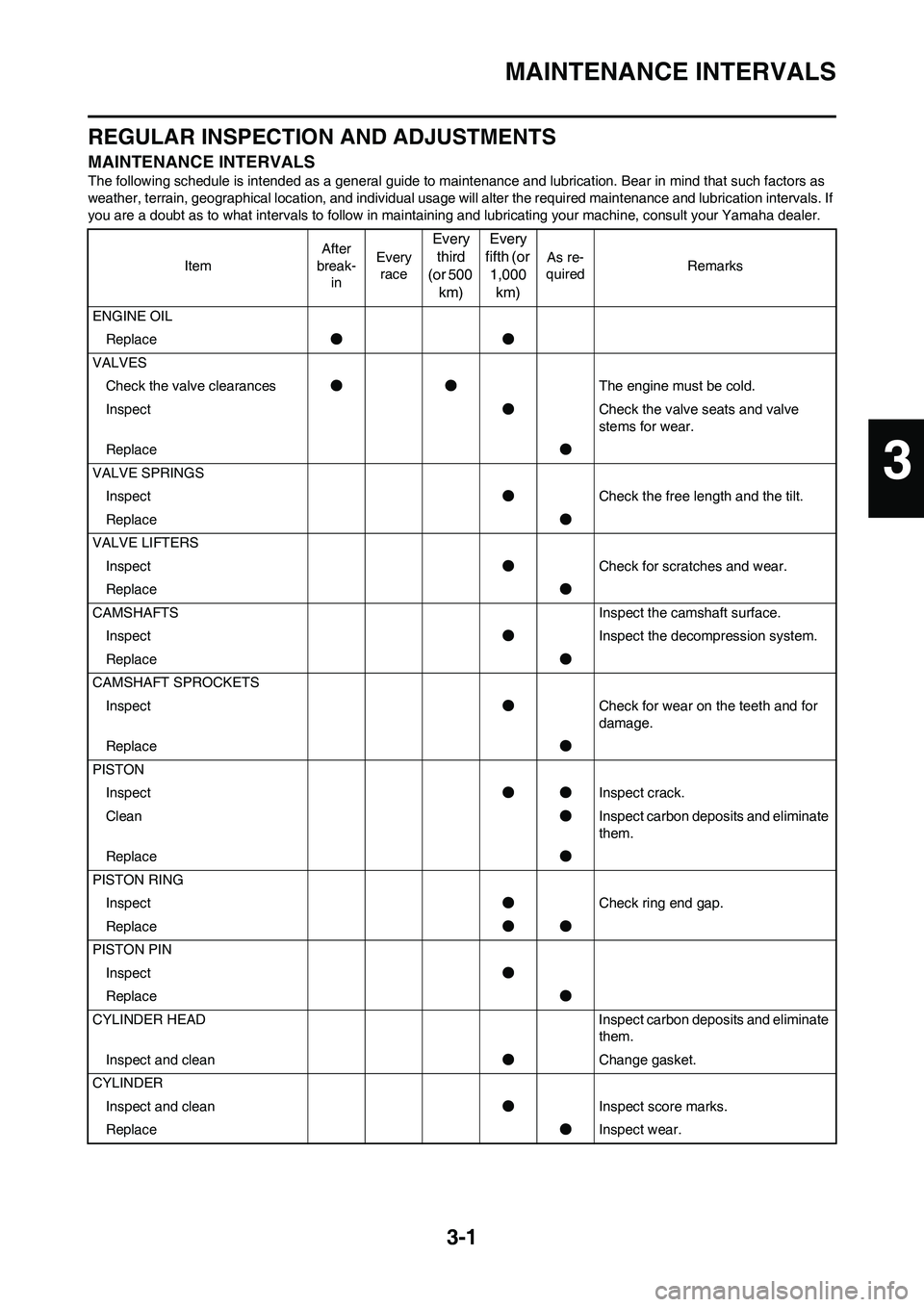
MAINTENANCE INTERVALS
The following schedule is intended as a general guide to maintenance and lubrication. Bear in mind that such factors as
weather, terrain, geographical location, and individual usage will alter the required maintenance and lubrication intervals. If
you are a doubt as to what intervals to follow in maintaining and lubricating your machine, consult your Yamaha dealer.
ItemAfter
break-
inEvery
race
Every
third
(or 500
km)Every
fifth (or
1,000
km)
As re-
quiredRemarks
ENGINE OIL
Replace●●
VALVES
Check the valve clearances●●The engine must be cold.
Inspect●Check the valve seats and valve
stems for wear.
Replace●
VALVE SPRINGS
Inspect●Check the free length and the tilt.
Replace●
VALVE LIFTERS
Inspect●Check for scratches and wear.
Replace●
CAMSHAFTS Inspect the camshaft surface.
Inspect●Inspect the decompression system.
Replace●
CAMSHAFT SPROCKETS
Inspect●Check for wear on the teeth and for
damage.
Replace●
PISTON
Inspect●●Inspect crack.
Clean●Inspect carbon deposits and eliminate
them.
Replace●
PISTON RING
Inspect●Check ring end gap.
Replace●●
PISTON PIN
Inspect●
Replace●
CYLINDER HEAD Inspect carbon deposits and eliminate
them.
Inspect and clean●Change gasket.
CYLINDER
Inspect and clean●Inspect score marks.
Replace●Inspect wear.
3
Page 48 of 190
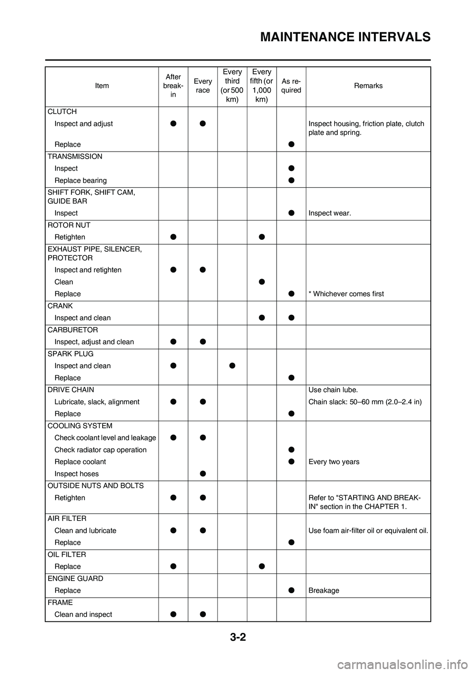
3-2
MAINTENANCE INTERVALS
CLUTCH
Inspect and adjust●●Inspect housing, friction plate, clutch
plate and spring.
Replace●
TRANSMISSION
Inspect●
Replace bearing●
SHIFT FORK, SHIFT CAM,
GUIDE BAR
Inspect●Inspect wear.
ROTOR NUT
Retighten●●
EXHAUST PIPE, SILENCER,
PROTECTOR
Inspect and retighten●●
Clean●
Replace●* Whichever comes first
CRANK
Inspect and clean●●
CARBURETOR
Inspect, adjust and clean●●
SPARK PLUG
Inspect and clean●●
Replace●
DRIVE CHAIN Use chain lube.
Lubricate, slack, alignment●●Chain slack: 50–60 mm (2.0–2.4 in)
Replace●
COOLING SYSTEM
Check coolant level and leakage●●
Check radiator cap operation●
Replace coolant●Every two years
Inspect hoses●
OUTSIDE NUTS AND BOLTS
Retighten●●Refer to "STARTING AND BREAK-
IN" section in the CHAPTER 1.
AIR FILTER
Clean and lubricate●●Use foam air-filter oil or equivalent oil.
Replace●
OIL FILTER
Replace●●
ENGINE GUARD
Replace●Breakage
FRAME
Clean and inspect●● ItemAfter
break-
inEvery
race
Every
third
(or 500
km)Every
fifth (or
1,000
km)
As re-
quiredRemarks
Page 51 of 190
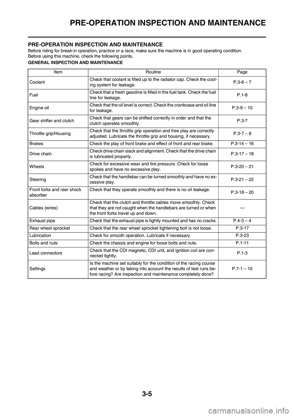
3-5
PRE-OPERATION INSPECTION AND MAINTENANCE
PRE-OPERATION INSPECTION AND MAINTENANCE
Before riding for break-in operation, practice or a race, make sure the machine is in good operating condition.
Before using this machine, check the following points.
GENERAL INSPECTION AND MAINTENANCE
Item Routine Page
CoolantCheck that coolant is filled up to the radiator cap. Check the cool-
ing system for leakage.P.3-6 – 7
FuelCheck that a fresh gasoline is filled in the fuel tank. Check the fuel
line for leakage.P.1-8
Engine oilCheck that the oil level is correct. Check the crankcase and oil line
for leakage.P.3-9 – 10
Gear shifter and clutchCheck that gears can be shifted correctly in order and that the
clutch operates smoothly.P.3-7
Throttle grip/HousingCheck that the throttle grip operation and free play are correctly
adjusted. Lubricate the throttle grip and housing, if necessary.P.3-7 – 8
Brakes Check the play of front brake and effect of front and rear brake. P.3-14 – 16
Drive chainCheck drive chain slack and alignment. Check that the drive chain
is lubricated properly.P.3-17 – 18
WheelsCheck for excessive wear and tire pressure. Check for loose
spokes and have no excessive play.P.3-20 – 21
SteeringCheck that the handlebar can be turned smoothly and have no ex-
cessive play.P.3-21 – 22
Front forks and rear shock
absorberCheck that they operate smoothly and there is no oil leakage.
P.3-18 – 20
Cables (wires)Check that the clutch and throttle cables move smoothly. Check
that they are not caught when the handlebars are turned or when
the front forks travel up and down.—
Exhaust pipe Check that the exhaust pipe is tightly mounted and has no cracks. P.4-3 – 4
Rear wheel sprocket Check that the rear wheel sprocket tightening bolt is not loose. P.3-17
Lubrication Check for smooth operation. Lubricate if necessary. P.3-23
Bolts and nuts Check the chassis and engine for loose bolts and nuts. P.1-11
Lead connectorsCheck that the CDI magneto, CDI unit, and ignition coil are con-
nected tightly.P.1-3
SettingsIs the machine set suitably for the condition of the racing course
and weather or by taking into account the results of test runs be-
fore racing? Are inspection and maintenance completely done?P.7-1 – 10