2009 YAMAHA YZ250F camshaft
[x] Cancel search: camshaftPage 10 of 190

CONTENTS
CHAPTER 1
GENERAL
INFORMATION
DESCRIPTION ................. 1-1
MACHINE
IDENTIFICATION ............. 1-2
INCLUDED PARTS .......... 1-2
IMPORTANT
INFORMATION................. 1-2
CHECKING OF
CONNECTION .................. 1-3
SPECIAL TOOLS ............. 1-4
CONTROL FUNCTIONS .. 1-8
STARTING AND
BREAK-IN ........................ 1-8
TORQUE-CHECK
POINTS........................... 1-11
CLEANING AND
STORAGE ...................... 1-12
CHAPTER 2
SPECIFICATIONS
GENERAL
SPECIFICATIONS ............ 2-1
MAINTENANCE
SPECIFICATIONS ............ 2-3
TIGHTENING
TORQUES ...................... 2-10
LUBRICATION
DIAGRAMS .................... 2-16
CABLE ROUTING
DIAGRAM ....................... 2-18
CHAPTER 3
REGULAR
INSPECTION AND
ADJUSTMENTS
MAINTENANCE
INTERVALS ...................... 3-1
PRE-OPERATION
INSPECTION AND
MAINTENANCE................ 3-5
ENGINE ............................ 3-6
CHASSIS ........................ 3-14
ELECTRICAL ................. 3-24
CHAPTER 4
ENGINE
SEAT, FUEL TANK AND
SIDE COVERS.................. 4-1
EXHAUST PIPE AND
SILENCER ........................ 4-3
RADIATOR ....................... 4-5
CARBURETOR................. 4-7
CAMSHAFTS.................. 4-14
CYLINDER HEAD........... 4-19
VALVES AND VALVE
SPRINGS ........................ 4-21
CYLINDER AND
PISTON ........................... 4-25
CLUTCH ......................... 4-29
OIL FILTER ELEMENT
AND WATER PUMP ....... 4-33
BALANCER .................... 4-37
OIL PUMP ....................... 4-39
KICK SHAFT AND
SHIFT SHAFT ................. 4-42
CDI MAGNETO............... 4-47
ENGINE REMOVAL ....... 4-49
CRANKCASE AND
CRANKSHAFT ............... 4-53
TRANSMISSION,
SHIFT CAM AND
SHIFT FORK................... 4-59
CHAPTER 5
CHASSIS
FRONT WHEEL AND
REAR WHEEL ..................5-1
FRONT BRAKE AND
REAR BRAKE ..................5-6
FRONT FORK ................. 5-16
HANDLEBAR..................5-24
STEERING ......................5-28
SWINGARM ....................5-31
REAR SHOCK
ABSORBER ....................5-36
CHAPTER 6
ELECTRICAL
ELECTRICAL
COMPONENTS AND
WIRING DIAGRAM ...........6-2
IGNITION SYSTEM...........6-3
THROTTLE POSITION
SENSOR SYSTEM ...........6-6
CHAPTER 7
TUNING
ENGINE.............................7-1
CHASSIS ..........................7-6
Page 25 of 190

2-3
MAINTENANCE SPECIFICATIONS
MAINTENANCE SPECIFICATIONS
ENGINEShock absorber:
Front shock absorber Coil spring/oil damper
Rear shock absorber Coil spring/gas, oil damper
Wheel travel: USA, CDN EUROPE, AUS, NZ, ZA
Front wheel travel 300 mm (11.8 in)←
Rear wheel travel 307 mm (12.1 in) 310 mm (12.2 in)
Electrical:
Ignition system CDI magneto
Item Standard Limit
Cylinder head:
Warp limit ---- 0.05 mm (0.002
in)
Cylinder:
Bore size 77.00–77.01 mm (3.0315–3.0319 in) ----
Out of round limit ---- 0.05 mm (0.002
in)
Camshaft:
Drive method Chain drive (Left) ----
Camshaft cap inside diameter 22.000–22.021 mm (0.8661–0.8670 in) ----
Camshaft outside diameter 21.959–21.972 mm (0.8645–0.8650 in) ----
Shaft-to-cap clearance 0.028–0.062 mm (0.0011–0.0024 in) 0.08 mm (0.003
in)
Cam dimensions
Intake "A" 30.246–30.346 mm (1.1908–1.1947 in) 30.146 mm
(1.1869 in)
Intake "B" 22.45–22.55 mm (0.8839–0.8878 in) 22.35 mm
(0.8799 in)
Exhaust "A" 30.399–30.499 mm (1.1968–1.2007 in) 30.299 mm
(1.1929 in)
Exhaust "B" 22.45–22.55 mm (0.8839–0.8878 in) 22.35 mm
(0.8799 in)
Page 26 of 190

2-4
MAINTENANCE SPECIFICATIONS
Camshaft runout limit ---- 0.03 mm
(0.0012 in)
Timing chain:
Timing chain type/No. of links 92RH2010-114M/114 ----
Timing chain adjustment method Automatic ----
Valve, valve seat, valve guide:
Valve clearance (cold)
IN 0.10–0.15 mm (0.0039–0.0059 in) ----
EX 0.17–0.22 mm (0.0067–0.0087 in) ----
Valve dimensions:
"A" head diameter (IN) 22.9–23.1 mm (0.9016–0.9094 in) ----
"A" head diameter (EX) 24.4–24.6 mm (0.9606–0.9685 in) ----
"B" face width (IN) 2.26 mm (0.089 in) ----
"B" face width (EX) 2.26 mm (0.089 in) ----
"C" seat width (IN) 0.9–1.1 mm (0.0354–0.0433 in) 1.6 mm (0.0630
in)
"C" seat width (EX) 0.9–1.1 mm (0.0354–0.0433 in) 1.6 mm (0.0630
in)
"D" margin thickness (IN) 0.8 mm (0.0315 in) ----
"D" margin thickness (EX) 0.7 mm (0.0276 in) ----Item Standard Limit
Page 32 of 190

2-10
TIGHTENING TORQUES
ELECTRICAL
TIGHTENING TORQUES
ENGINE
△- marked portion shall be checked for torque tightening after break-in or before each race.
Clutch lever free play (lever end) 7–12 mm (0.28–0.47 in) ----
Throttle grip free play 3–5 mm (0.12–0.20 in) ----Item Standard Limit
Item Standard Limit
Ignition system:
Advancer type Electrical ----
CDI:
Magneto-model (stator)/manufacturer 5XC-10/YAMAHA ----
Charging coil 1 resistance (color) 720–1,080 Ωat 20 °C (68 °F) (Green–
Brown)----
Charging coil 2 resistance (color) 44–66 Ωat 20 °C (68 °F) (Black–Pink) ----
Pickup coil resistance (color) 248–372 Ωat 20 °C (68 °F) (White–Red) ----
CDI unit-model/manufacturer 5XC-R0/YAMAHA (For USA and CDN) ----
5XC-S0/YAMAHA (Except for USA and
CDN)----
Ignition coil:
Model/manufacturer 5UL-10/DENSO ----
Minimum spark gap 6 mm (0.24 in) ----
Primary coil resistance 0.08–0.10 Ωat 20 °C (68 °F) ----
Secondary coil resistance 4.6–6.8 kΩat 20 °C (68 °F) ----
Part to be tightened Thread size Q'tyTightening torque
Nm m•kg ft•lb
Spark plug M10S × 1.0 1 13 1.3 9.4
Camshaft cap M6 × 1.0 10 10 1.0 7.2
Cylinder head blind plug screw M12 × 1.0 1 28 2.8 20
Cylinder head (stud bolt) M6 × 1.0 2 7 0.7 5.1
Cylinder head (stud bolt) M8 × 1.25 1 15 1.5 11
Cylinder head (bolt) M9 × 1.25 4 38 3.8 27
Cylinder head (nut) M6 × 1.0 2 10 1.0 7.2
Cylinder head cover M6 × 1.0 2 10 1.0 7.2
Cylinder M6 × 1.0 1 10 1.0 7.2
Balancer weight M6 × 1.0 2 10 1.0 7.2
Balancer shaft driven gear M14 × 1.0 1 50 5.0 36
Timing chain guide (intake side) M6 × 1.0 2 10 1.0 7.2
Timing chain tensioner M6 × 1.0 2 10 1.0 7.2
Timing chain tensioner cap bolt M6 × 1.0 1 7 0.7 5.1
Impeller M8 × 1.25 1 14 1.4 10
Radiator hose clamp M6 × 1.0 10 2 0.2 1.4
Coolant drain bolt M6 × 1.0 1 10 1.0 7.2
Water pump housing M6 × 1.0 4 10 1.0 7.2
Radiator M6 × 1.0 6 10 1.0 7.2
Page 38 of 190

2-16
LUBRICATION DIAGRAMS
LUBRICATION DIAGRAMS
1. Oil filter element
2. Oil pump
3. Drive axle
4. Main axle
5. Intake camshaft
6. Exhaust camshaft
7. Oil tank
8. Oil delivery pipe
A. To oil tank
Page 47 of 190

3-1
MAINTENANCE INTERVALS
REGULAR INSPECTION AND ADJUSTMENTS
MAINTENANCE INTERVALS
The following schedule is intended as a general guide to maintenance and lubrication. Bear in mind that such factors as
weather, terrain, geographical location, and individual usage will alter the required maintenance and lubrication intervals. If
you are a doubt as to what intervals to follow in maintaining and lubricating your machine, consult your Yamaha dealer.
ItemAfter
break-
inEvery
race
Every
third
(or 500
km)Every
fifth (or
1,000
km)
As re-
quiredRemarks
ENGINE OIL
Replace●●
Inspect●●
OIL FILTER ELEMENT, OIL
STRAINER
Clean●
VALVES
Check the valve clearances●●The engine must be cold.
Inspect●Check the valve seats and valve
stems for wear.
Replace●
VALVE SPRINGS
Inspect●Check the free length and the tilt.
Replace●
VALVE LIFTERS
Inspect●Check for scratches and wear.
Replace●
CAMSHAFTS Inspect the camshaft surface.
Inspect●Inspect the decompression system.
Replace●
TIMING CHAIN SPROCKETS,
TIMING CHAIN
Inspect●Check for wear on the teeth and for
damage.
Replace●
PISTON
Inspect●●Inspect crack.
Clean●Inspect carbon deposits and eliminate
them.
Replace●
PISTON RING
Inspect●Check ring end gap.
Replace●●
PISTON PIN
Inspect●
Replace●
CYLINDER HEAD Inspect carbon deposits and eliminate
them.
Inspect and clean●Change gasket.
3
Page 57 of 190
3-11
ENGINE
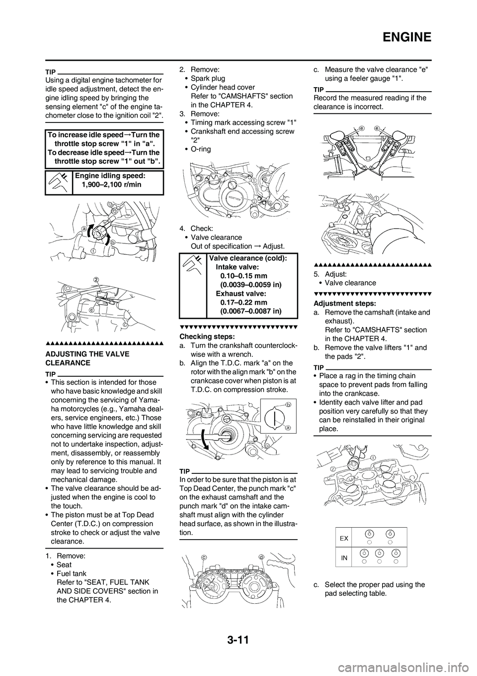
Using a digital engine tachometer for
idle speed adjustment, detect the en-
gine idling speed by bringing the
sensing element "c" of the engine ta-
chometer close to the ignition coil "2".
ADJUSTING THE VALVE
CLEARANCE
• This section is intended for those
who have basic knowledge and skill
concerning the servicing of Yama-
ha motorcycles (e.g., Yamaha deal-
ers, service engineers, etc.) Those
who have little knowledge and skill
concerning servicing are requested
not to undertake inspection, adjust-
ment, disassembly, or reassembly
only by reference to this manual. It
may lead to servicing trouble and
mechanical damage.
• The valve clearance should be ad-
justed when the engine is cool to
the touch.
• The piston must be at Top Dead
Center (T.D.C.) on compression
stroke to check or adjust the valve
clearance.
1. Remove:
• Seat
• Fuel tank
Refer to "SEAT, FUEL TANK
AND SIDE COVERS" section in
the CHAPTER 4.2. Remove:
• Spark plug
• Cylinder head cover
Refer to "CAMSHAFTS" section
in the CHAPTER 4.
3. Remove:
• Timing mark accessing screw "1"
• Crankshaft end accessing screw
"2"
• O-ring
4. Check:
• Valve clearance
Out of specification→Adjust.
Checking steps:
a. Turn the crankshaft counterclock-
wise with a wrench.
b. Align the T.D.C. mark "a" on the
rotor with the align mark "b" on the
crankcase cover when piston is at
T.D.C. on compression stroke.
In order to be sure that the piston is at
Top Dead Center, the punch mark "c"
on the exhaust camshaft and the
punch mark "d" on the intake cam-
shaft must align with the cylinder
head surface, as shown in the illustra-
tion.
c. Measure the valve clearance "e"
using a feeler gauge "1".
Record the measured reading if the
clearance is incorrect.
5. Adjust:
• Valve clearance
Adjustment steps:
a. Remove the camshaft (intake and
exhaust).
Refer to "CAMSHAFTS" section
in the CHAPTER 4.
b. Remove the valve lifters "1" and
the pads "2".
• Place a rag in the timing chain
space to prevent pads from falling
into the crankcase.
• Identity each valve lifter and pad
position very carefully so that they
can be reinstalled in their original
place.
c. Select the proper pad using the
pad selecting table. To increase idle speed→Turn the
throttle stop screw "1" in "a".
To decrease idle speed→Turn the
throttle stop screw "1" out "b".
Engine idling speed:
1,900–2,100 r/min
Valve clearance (cold):
Intake valve:
0.10–0.15 mm
(0.0039–0.0059 in)
Exhaust valve:
0.17–0.22 mm
(0.0067–0.0087 in)
Page 58 of 190

3-12
ENGINE
The thickness "a" of each pad is indi-
cated in hundredths of millimeters on
the pad upper surface.
d. Round off the last digit of the in-
stalled pad number to the nearest
increment.
EXAMPLE:
Installed pad number = 148
Rounded off value = 150
Pads can only be selected in 0.05
mm increments.
e. Locate the rounded-off value and
the measured valve clearance in
the chart "PAD SELECTION TA-
BLE". The field where these two
coordinates intersect shows the
new pad number to use.
Use the new pad number only as a
guide when verifying the valve clear-
ance adjustment.
f. Install the new pads "3" and the
valve lifters "4".
• Apply the engine oil on the valve lift-
ers.
• Apply the molybdenum disulfide oil
on the valve stem ends.
• Valve lifter must turn smoothly
when rotated with a finger.
• Be careful to reinstall valve lifters
and pads in their original place.
g. Install the camshafts (exhaust
and intake).
Refer to "CAMSHAFTS" section
in the CHAPTER 4.
Pad rangePad Availabili-
ty: 25 incre-
ments
No.
120–
No.
2401.20
mm–
2.40
mmPads are avail-
able in 0.05 mm
increments
Last digit of pad
numberRounded valve
0, 1 or 2 0
4, 5 or 6 5
8 or 9 10