Page 110 of 150

8-30
1
2
3
4
5
6
78
9
10
11
tenance.
NOTICE
ECB00480
The carburetor has been set and extensively
tested at the Yamaha factory. Changing these
settings without sufficient technical knowl-
edge may result in poor performance of or
damage to the engine.
EBU24030
Checking the engine idling speed
A special tester is needed to check the engine
idling speed on this model.
Therefore, take the ATV to a Yamaha dealer to
have the engine idling speed checked and adjust-
ed.
EBU24044
Adjusting the throttle cable free play
The throttle cable free play should be checked
and, if necessary, adjusted at the intervals speci-
fied in the periodic maintenance and lubrication
chart.
The throttle cable free play should measure 2.0–4.0 mm (0.08–0.16 in) at the throttle lever. Period-
ically check the throttle cable free play and, if nec-
essary, adjust it as follows.
TIP
The engine idling speed must be checked, and ad-
justed if necessary, before adjusting the throttle ca-
ble free play.
1. Loosen the locknut.
2. To increase the throttle cable free play, turn
the throttle cable free play adjusting bolt in di-
rection (a). To decrease the throttle cable free
play, turn the adjusting bolt in direction (b).
Engine idling speed:
1750–1850 r/min
Page 111 of 150

8-31
1
2
3
4
5
6
78
9
10
11
3. Tighten the locknut.
EBU24060
Valve clearance
The valve clearance changes with use, resulting in
improper air-fuel mixture and/or engine noise. To
prevent this from occurring, the valve clearance
must be adjusted by a Yamaha dealer at the inter-
vals specified in the periodic maintenance and lu-
brication chart.
EBU24130
Checking the front and rear brake pads
The front and rear brake pads must be checked for
wear at the intervals specified in the periodic main-
tenance and lubrication chart.
EBU27711
Front brake pads
Each brake pad is provided with wear indicator
grooves, which allow you to check the brake pad
wear without having to disassemble the brake. To
check the brake pad wear, check the wear indica-
tor grooves. If a brake pad has worn to the point
that the wear indicator grooves are almost in con-
tact with the disc plate, have a Yamaha dealer re-
place the brake pads as a set.
1. Locknut
2. Throttle cable free play adjusting bolt
3. Throttle lever free play
3 2
1
(a)(b)
Page 115 of 150

8-35
1
2
3
4
5
6
78
9
10
11
6. Install the brake fluid reservoir bracket bolt.
Observe these precautions:
�
When checking the fluid level, make sure that
the top of the brake fluid reservoir is level.
�
Use only the recommended quality brake fluid,
otherwise the rubber seals may deteriorate,
causing leakage and poor braking performance.
�
Refill with the same type of brake fluid. Mixing
fluids may result in a harmful chemical reaction
and lead to poor braking performance.
�
Be careful that water does not enter the brake
fluid reservoir when refilling. Water will signifi-
cantly lower the boiling point of the fluid and may
result in vapor lock.
�
Brake fluid may deteriorate painted surfaces or
plastic parts. Always clean up spilled fluid imme-
diately.
�
As the brake pads wear, it is normal for the brake
fluid level to gradually go down. However, if the
brake fluid level goes down suddenly, have a
Yamaha dealer check the cause.
EBU24291
Changing the brake fluid
Have a Yamaha dealer change the brake fluid at
the intervals specified in the TIP after the periodic
maintenance and lubrication chart. In addition,
have the oil seals of the master cylinders and cali-
pers as well as the brake hoses replaced at the in-
tervals listed below or whenever they are damaged
or leaking.
�
Oil seals: Replace every two years.
�
Brake hoses: Replace every four years.
1. Frame
2. Projection
3. Brake fluid reservoir bracket
4. Bolt
Recommended brake fluid:
DOT 4
2
3
1
4
Page 117 of 150
8-37
1
2
3
4
5
6
78
9
10
11
WARNING
EWB02110
Operating with improperly serviced or adjust-
ed brakes could cause loss of braking ability,
which could lead to an accident.
After servicing:
�
Make sure the brakes operate smoothly and
that the brake pedal position is correct.
�
Make sure the brakes do not drag.
�
Make sure the brakes are not spongy. All air
must be bled from the brake system.
Replacement of brake components requires
professional knowledge. These procedures
should be performed by a Yamaha dealer.
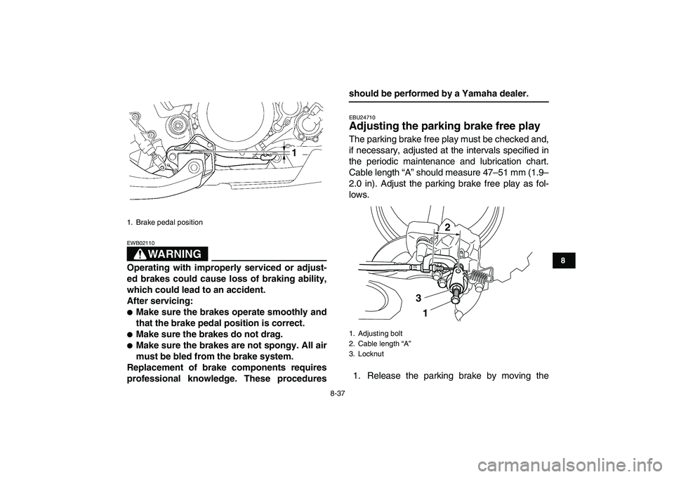
EBU24710
Adjusting the parking brake free play
The parking brake free play must be checked and,
if necessary, adjusted at the intervals specified in
the periodic maintenance and lubrication chart.
Cable length “A” should measure 47–51 mm (1.9–
2.0 in). Adjust the parking brake free play as fol-
lows.
1. Release the parking brake by moving the
1. Brake pedal position
1
1. Adjusting bolt
2. Cable length “A”
3. Locknut
2
3
1
Page 118 of 150

8-38
1
2
3
4
5
6
78
9
10
11
parking brake lever to the right.
2. Fully loosen the locknut and the adjusting bolt
at the rear brake caliper.
3. Loosen the locknut on the brake cable.
4. Turn the adjusting nut on the brake cable in di-
rection (a) to increase the cable length, and in
direction (b) to decrease it.
TIP
If the cable length cannot be adjusted to specifica-
tion, consult a Yamaha dealer.
5. Tighten the locknut on the brake cable.6. Turn in the adjusting bolt at the rear brake cal-
iper until it feels tight, then turn it out 1/8 turn
and tighten its locknut to the specified torque.
NOTICE
ECB00520
When tightening the locknut, hold the adjust-
ing bolt with a wrench so that it does not turn
together with the locknut.
WARNING
EWB02090
Operating with improperly serviced or adjust-
ed brakes could cause the brakes to malfunc-
tion, resulting in reduced braking
performance. This could increase the chance
of a collision or accident. After adjusting the
parking brake free play, block the rear of the
ATV off the ground and spin the rear wheels.
Check to make sure there is no brake drag. If
brake drag is noticed, perform the adjustment
again.
1. Locknut
2. Adjusting nut
(a)
(b)
12
Tightening torque:
Locknut (rear brake caliper):
16 Nm (1.6 m·kgf, 12 ft·lbf)
Page 120 of 150
8-40
1
2
3
4
5
6
78
9
10
11
1. To increase the clutch lever free play, turn the
adjusting bolt at the clutch lever in direction
(a), and to decrease it, turn the bolt in direction
(b).
If the specified free play cannot be obtained,
proceed with the following steps.
2. Fully turn the adjusting bolt at the clutch lever
in direction (a) to loosen the clutch cable.
3. Loosen the locknut.
4. To increase the clutch lever free play, turn the
adjusting nut in direction (a), and to decrease
it, turn the nut in direction (b).5. Tighten the locknut.
TIP
If the specified free play cannot be obtained as de-
scribed above or if the clutch does not operate cor-
rectly, have a Yamaha dealer check the internal
clutch mechanism.
1. Clutch lever free play
2. Clutch lever free play adjusting bolt
1
(a)
(b)
2
1. Locknut
2. Clutch lever free play adjusting nut
(a)
(b)
2
1
Page 131 of 150
8-51
1
2
3
4
5
6
78
9
10
11
4. Remove the headlight bulb holder by pushing
it in and turning it counterclockwise, and then
remove the defective bulb.WARNING
EWB02230
Do not touch a headlight bulb when it is on or
immediately after it is turned off. You can be
burned or a fire could start if the bulb touches
something flammable. Wait for the bulb to cool
before touching or removing it.
5. Place a new headlight bulb into position.
1. Headlight bulb holder cover
2. Headlight coupler
1
2
1. Headlight bulb holder
1
Page 132 of 150
8-52
1
2
3
4
5
6
78
9
10
11
NOTICE
ECB00650
Do not touch the glass part of the headlight
bulb to keep it free from oil, otherwise the
transparency of the glass, the luminosity of the
bulb, and the bulb life will be adversely affect-
ed. Thoroughly clean off any dirt and finger-
prints on the headlight bulb using a cloth
moistened with alcohol or thinner.
6. Install the headlight bulb holder by pushing it
in and turning it clockwise.
7. Install the headlight bulb holder cover.8. Connect the headlight coupler.
9. Install the headlight unit by installing the bolts.
10. Adjust the headlight beam if necessary.
EBU25551
Adjusting a headlight beam
NOTICE
ECB00690
It is advisable to have a Yamaha dealer make
this adjustment.
To raise a headlight beam, turn the headlight beam
adjusting screw in direction (a).
To lower a headlight beam, turn the adjusting
screw in direction (b).
1. Do not touch the glass part of the bulb.
1
1. Headlight beam adjusting screw
1(a)
(b)
, and to decrease it, turn the bolt in direction
(b).
If the spe")

