Page 6 of 84

TABLE OF CONTENTS
SAFETY INFORMATION
...................1-1
DESCRIPTION
...................................2-1
Left view ...........................................2-1
Right view .........................................2-2
Controls and instruments..................2-3
INSTRUMENT AND CONTROL
FUNCTIONS
........................................3-1
Immobilizer system ..........................3-1
Main switch/steering lock .................3-2
Indicator and warning lights .............3-3
Multi-function meter unit ..................3-4
Handlebar switches .........................3-7
Clutch lever ......................................3-9
Shift pedal ........................................3-9
Brake lever ....................................3-10
Brake pedal ...................................3-10
Fuel tank cap .................................3-10
Fuel ................................................3-11
Catalytic converter .........................3-12
Rider seat ......................................3-13
Helmet holder ................................3-14
Adjusting the shock absorber
assembly ....................................3-14
Sidestand .......................................3-16
Ignition circuit cut-off system .........3-16
FOR YOUR SAFETY –
PRE-OPERATION CHECKS
...............4-1
OPERATION AND IMPORTANT
RIDING POINTS
.................................. 5-1
Starting the engine .......................... 5-1
Shifting ............................................ 5-2
Tips for reducing fuel
consumption ................................ 5-3
Engine break-in ............................... 5-3
Parking ............................................ 5-4
PERIODIC MAINTENANCE AND
ADJUSTMENT
.................................... 6-1
Owner’s tool kit ................................ 6-1
Periodic maintenance chart for the
emission control system .............. 6-2
General maintenance and
lubrication chart ........................... 6-3
Removing and installing the
panel ............................................ 6-6
Checking the spark plugs ................ 6-6
Engine oil and oil filter cartridge ...... 6-7
Replacing the air filter element ...... 6-11
Checking the engine idling
speed ......................................... 6-11
Checking the throttle cable free
play ............................................ 6-12
Valve clearance ............................. 6-12
Tires .............................................. 6-12
Cast wheels ................................... 6-14
Adjusting the clutch lever free
play ............................................ 6-14Adjusting the brake lever free
play ............................................ 6-15
Adjusting the rear brake light
switch ......................................... 6-16
Checking the front and rear brake
pads ........................................... 6-16
Checking the brake fluid level ....... 6-17
Changing the brake fluid ............... 6-18
Drive belt slack .............................. 6-18
Checking and lubricating the
cables ........................................ 6-20
Checking and lubricating the
throttle grip and cable ................ 6-20
Checking and lubricating the
brake and shift pedals ............... 6-21
Checking and lubricating the
brake and clutch levers .............. 6-21
Checking and lubricating the
sidestand ................................... 6-22
Lubricating the rear suspension .... 6-22
Checking the front fork .................. 6-23
Checking the steering ................... 6-23
Checking the wheel bearings ........ 6-24
Battery ........................................... 6-24
Replacing the fuses ...................... 6-26
Replacing the headlight bulb ........ 6-27
Replacing the tail/brake light
bulb ............................................ 6-28
Replacing a turn signal light
bulb ............................................ 6-29
Page 21 of 84

INSTRUMENT AND CONTROL FUNCTIONS
3-7
2
34
5
6
7
8
9
do not start the engine, take the
vehicle, the code re-registering
key and both standard keys to a
Yamaha dealer and have the stan-
dard keys re-registered.
If the odometer/tripmeter/clock display
indicates any error codes, note the
code number, and then have a Yamaha
dealer check the vehicle.
NOTICE
ECA11590
If the display indicates an error
code, the vehicle should be checked
as soon as possible in order to avoid
engine damage.
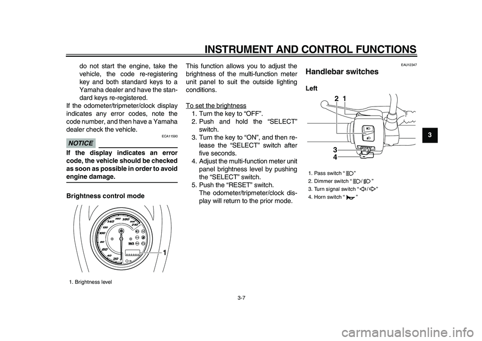
Brightness control mode
This function allows you to adjust the
brightness of the multi-function meter
unit panel to suit the outside lighting
conditions.
To set the brightness
1. Turn the key to “OFF”.
2. Push and hold the “SELECT”
switch.
3. Turn the key to “ON”, and then re-
lease the “SELECT” switch after
five seconds.
4. Adjust the multi-function meter unit
panel brightness level by pushing
the “SELECT” switch.
5. Push the “RESET” switch.
The odometer/tripmeter/clock dis-
play will return to the prior mode.
EAU12347
Handlebar switches
Left
1. Brightness level
1
1. Pass switch “ ”
2. Dimmer switch “ / ”
3. Turn signal switch “ / ”
4. Horn switch “ ”
3
41 2
Page 29 of 84

INSTRUMENT AND CONTROL FUNCTIONS
3-15
2
34
5
6
7
8
9
NOTICE
ECA10101
To avoid damaging the mechanism,
do not attempt to turn beyond the
maximum or minimum settings.
Adjust the spring preload as follows.
1. Remove panel A. (See page 6-6.)
2. To increase the spring preload and
thereby harden the suspension,
turn the adjusting ring in direction
(a). To decrease the spring pre-
load and thereby soften the sus-
pension, turn the adjusting ring in
direction (b).
TIP
Align the appropriate notch in the ad-
justing ring with the position indicator
on the shock absorber.
3. Install the panel.
WARNING
EWA10221
This shock absorber assembly con-
tains highly pressurized nitrogen
gas. Read and understand the fol-
lowing information before handling
the shock absorber assembly.
�
Do not tamper with or attempt toopen the cylinder assembly.
�
Do not subject the shock ab-
sorber assembly to an open
flame or other high heat source.
This may cause the unit to ex-
plode due to excessive gas
pressure.
�
Do not deform or damage the
cylinder in any way. Cylinder
damage will result in poor
damping performance.
�
Do not dispose of a damaged or
worn-out shock absorber as-
sembly yourself. Take the shock
absorber assembly to a Yamaha
dealer for any service.
1. Special wrench
2. Position indicator
Spring preload setting:
Minimum (soft):
1
Standard:
4
Maximum (hard):
9
1
2
(a)
(b)
123456789