Page 22 of 102

INSTRUMENT AND CONTROL FUNCTIONS
3-8
3
EAU46763
Multi-function meter unit
WARNING
EWA12422
Be sure to stop the vehicle before
making any setting changes to the
multi-function meter unit. Changing
settings while riding can distract the
operator and increase the risk of anaccident.The multi-function meter unit is
equipped with the following:
�
a speedometer
�
a tachometer
�
an odometer
�
two tripmeters (which show the
distance traveled since they were
last set to zero)
�
a fuel reserve tripmeter (which
shows the distance traveled since
the left segment of the fuel meter
started flashing)
�
a clock
�
a fuel meter
�
a coolant temperature display
�
a self-diagnosis device
TIP�
Be sure to turn the key to “ON” be-
fore using the “SELECT” and “RE-
SET” buttons.
�
For the U.K. only: To switch the
speedometer and odometer/trip-
meter displays between kilometers
and miles, press the “SELECT”button for at least one second.Tachometer
The electric tachometer allows the rider
to monitor the engine speed and keep it
within the ideal power range.
When the key is turned to “ON”, the ta-
chometer needle will sweep once
across the r/min range and then return
to zero r/min in order to test the electri-
cal circuit.
NOTICE
ECA10031
Do not operate the engine in the ta-
chometer red zone.Red zone: 11666 r/min and above
1. Fuel meter
2. Coolant temperature display
3. Speedometer
4. Tachometer
5. Odometer/tripmeter/fuel reserve tripmeter
6.“SELECT” button
7.“RESET” button
8. Clock
1
8
2
3
4
7
6
5
1. Tachometer
2. Tachometer red zone
ABS1
2
U36CE0E0.book Page 8 Friday, December 5, 2008 2:33 PM
Page 24 of 102
 as the fuel level
decr")
INSTRUMENT AND CONTROL FUNCTIONS
3-10
3The fuel meter indicates the amount of
fuel in the fuel tank. The display seg-
ments of the fuel meter disappear to-
wards “E” (Empty) as the fuel level
decreases. When the last segment on
the left starts flashing, refuel as soon as
possible.
TIPThis fuel meter is equipped with a self-
diagnosis system. If a problem is de-
tected in the electrical circuit, the follow-
ing cycle is repeated until the
malfunction is corrected: fuel level seg-
ments and symbol“” flash eight
times, then go off for approximately 3
seconds. If this occurs, have a Yamahadealer check the electrical circuit.Coolant temperature mode
The coolant temperature display indi-
cates the temperature of the coolant.
NOTICE
ECA10021
Do not continue to operate the en-gine if it is overheating.Self-diagnosis device
This model is equipped with a self-diag-
nosis device for various electrical cir-
cuits.
If a problem is detected in any of those
circuits, the engine trouble warning light
will come on and the display will indi-
cate an error code.
The self-diagnosis device also detects
problems in the immobilizer system cir-
cuits.
If a problem is detected in the immobi-
lizer system circuits, the immobilizer
system indicator light will flash and the
display will indicate an error code.1. Coolant temperature display
1
1. Error code display1
U36CE0E0.book Page 10 Friday, December 5, 2008 2:33 PM
Page 26 of 102

INSTRUMENT AND CONTROL FUNCTIONS
3-12
3
EAU12348
Handlebar switches LeftRight
EAU12350
Pass switch“”
Press this switch to flash the headlight.
EAU12400
Dimmer switch“/”
Set this switch to“” for the high
beam and to“” for the low beam.
EAU12460
Turn signal switch“/”
To signal a right-hand turn, push this
switch to“”. To signal a left-hand
turn, push this switch to“”. When re-
leased, the switch returns to the centerposition. To cancel the turn signal
lights, push the switch in after it has re-
turned to the center position.
EAU12500
Horn switch“”
Press this switch to sound the horn.
EAU12660
Engine stop switch“/”
Set this switch to“” before starting
the engine. Set this switch to“” to
stop the engine in case of an emergen-
cy, such as when the vehicle overturns
or when the throttle cable is stuck.
EAU12711
Start switch“”
Push this switch to crank the engine
with the starter. See page 5-1 for start-
ing instructions prior to starting the en-
gine.
EAU44710
The engine trouble warning light and
ABS warning light (ABS model only) will
come on when the key is turned to “ON”
and the start switch is pushed, but this
does not indicate a malfunction.
1. Pass switch“”
2. Dimmer switch“/”
3. Turn signal switch“/”
4. Horn switch“”
5. Hazard switch“”
1. Engine stop switch“/”
2. Start switch“”
U36CE0E0.book Page 12 Friday, December 5, 2008 2:33 PM
Page 28 of 102

INSTRUMENT AND CONTROL FUNCTIONS
3-14
3
EAU26823
Brake lever The brake lever is located at the right
handlebar grip. To apply the front
brake, pull the lever toward the handle-
bar grip.
The brake lever is equipped with a
brake lever position adjusting dial. To
adjust the distance between the brake
lever and the handlebar grip, turn the
adjusting dial while holding the lever
pushed away from the handlebar grip.
Make sure that the appropriate setting
on the adjusting dial is aligned with
the“” mark on the brake lever.
EAU12941
Brake pedal The brake pedal is on the right side of
the motorcycle. To apply the rear
brake, press down on the brake pedal.
EAU47520
ABS (for ABS models) The Yamaha ABS (Anti-lock Brake
System) features a dual electronic con-
trol system, which acts on the front and
rear brakes independently. The ABS is
monitored by an ECU, which will have
recourse to manual braking if a mal-
function occurs.
WARNING
EWA10090
�
The ABS performs best on long
braking distances.
�
On certain (rough or gravel)
roads, the braking distance may
be longer with than without the
ABS. Therefore, always keep a
sufficient distance to the vehicle
ahead to match the ridingspeed.
TIP�
The ABS performs a self-diagno-
sis test for a few seconds each
time the vehicle first starts off after
the main switch was turned on.
During this test, a “clicking” noise
can be heard from under the seat,
and if the brake lever or brake ped-
1. Brake lever
2. Brake lever position adjusting dial
3.“” mark
4. Distance between brake lever and handlebar
grip
1. Brake pedal
1
U36CE0E0.book Page 14 Friday, December 5, 2008 2:33 PM
Page 30 of 102

INSTRUMENT AND CONTROL FUNCTIONS
3-16
3
TIPThe fuel tank cap cannot be closed un-
less the key is in the lock. In addition,
the key cannot be removed if the cap isnot properly closed and locked.
WARNING
EWA11091
Make sure that the fuel tank cap is
properly closed after filling fuel.Leaking fuel is a fire hazard.
EAU13221
Fuel Make sure there is sufficient gasoline in
the tank.
WARNING
EWA10881
Gasoline and gasoline vapors are
extremely flammable. To avoid fires
and explosions and to reduce the
risk of injury when refueling, followthese instructions.
1. Before refueling, turn off the en-
gine and be sure that no one is sit-
ting on the vehicle. Never refuel
while smoking, or while in the vi-
cinity of sparks, open flames, or
other sources of ignition such as
the pilot lights of water heaters and
clothes dryers.
2. Do not overfill the fuel tank. When
refueling, be sure to insert the
pump nozzle into the fuel tank filler
hole. Stop filling when the fuel
reaches the bottom of the filler
tube. Because fuel expands when
it heats up, heat from the engine or
the sun can cause fuel to spill out
of the fuel tank.3. Wipe up any spilled fuel immedi-
ately. NOTICE: Immediately wipe
off spilled fuel with a clean, dry,
soft cloth, since fuel may deteri-
orate painted surfaces or plastic
parts.
[ECA10071]
4. Be sure to securely close the fuel
tank cap.
WARNING
EWA15151
Gasoline is poisonous and can
cause injury or death. Handle gaso-
line with care. Never siphon gaso-
line by mouth. If you should swallow
some gasoline or inhale a lot of gas-
oline vapor, or get some gasoline in
your eyes, see your doctor immedi-1. Fuel tank filler tube
2. Fuel level
1
2
U36CE0E0.book Page 16 Friday, December 5, 2008 2:33 PM
Page 32 of 102

INSTRUMENT AND CONTROL FUNCTIONS
3-18
3
EAU13433
Catalytic converter This model is equipped with a catalytic
converter in the exhaust system.
WARNING
EWA10862
The exhaust system is hot after op-
eration. To prevent a fire hazard or
burns:�
Do not park the vehicle near
possible fire hazards such as
grass or other materials that
easily burn.
�
Park the vehicle in a place
where pedestrians or children
are not likely to touch the hot
exhaust system.
�
Make sure that the exhaust sys-
tem has cooled down before do-
ing any maintenance work.
�
Do not allow the engine to idle
more than a few minutes. Long
idling can cause a build-up ofheat.
NOTICE
ECA10701
Use only unleaded gasoline. The use
of leaded gasoline will cause unre-
pairable damage to the catalyticconverter.
EAU32980
Seat To remove the seat
1. Insert the key into the seat lock,
and then turn it counterclockwise.
2. While holding the key in that posi-
tion, lift the rear of the seat up, and
then pull the seat off.
To install the seat
1. Insert the projection on the front of
the seat into the seat holder as
shown.1. Seat lock
2. Unlock.
12
U36CE0E0.book Page 18 Friday, December 5, 2008 2:33 PM
Page 33 of 102

INSTRUMENT AND CONTROL FUNCTIONS
3-19
3
2. Push the rear of the seat down to
lock it in place.
3. Remove the key.
TIPMake sure that the seat is properly se-cured before riding.
EAU46750
Helmet holder The helmet holder is located under the
seat. A helmet holding cable is provid-
ed in the owner’s tool kit to secure a
helmet to the helmet holder.
To secure a helmet to the helmet
holder
1. Remove the seat. (See page
3-18.)
2. Pass the helmet holding cable
through the buckle on the helmet
strap as shown, and then hook the
cable loop over the helmet holder.3. Place the helmet on the right side
of the vehicle, and then install the
seat. WARNING! Never ride with
a helmet attached to the helmet
holder, since the helmet may hit
objects, causing loss of control
and possibly an accident.
[EWA10161]
To release the helmet from the hel-
met holder
Remove the seat, remove the helmet
holding cable from the helmet holder
and the helmet, and then install the
seat.
1. Projection
2. Seat holder
1
2
1. Helmet holder
2. Owner’s tool kit
3. Helmet holding cable
2
3
1
1. Helmet
2. Helmet holding cable
3. Helmet holder
123
U36CE0E0.book Page 19 Friday, December 5, 2008 2:33 PM
Page 34 of 102
INSTRUMENT AND CONTROL FUNCTIONS
3-20
3
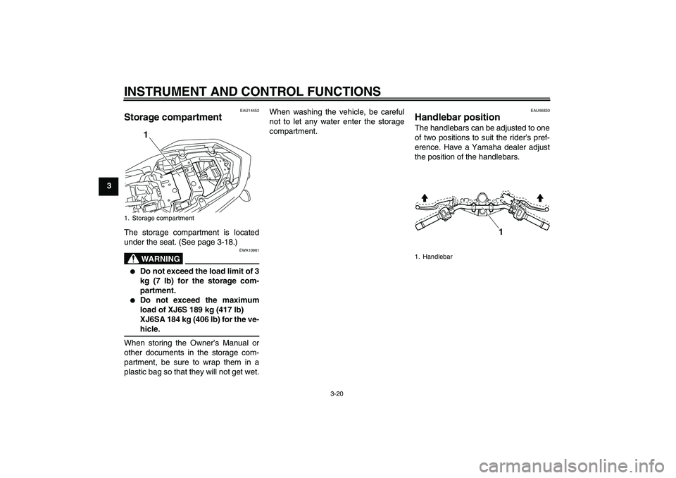
EAU14452
Storage compartment The storage compartment is located
under the seat. (See page 3-18.)
WARNING
EWA10961
�
Do not exceed the load limit of 3
kg (7 lb) for the storage com-
partment.
�
Do not exceed the maximum
load of XJ6S 189 kg (417 lb)
XJ6SA 184 kg (406 lb) for the ve-hicle.
When storing the Owner’s Manual or
other documents in the storage com-
partment, be sure to wrap them in a
plastic bag so that they will not get wet.When washing the vehicle, be careful
not to let any water enter the storage
compartment.
EAU46830
Handlebar position The handlebars can be adjusted to one
of two positions to suit the rider’s pref-
erence. Have a Yamaha dealer adjust
the position of the handlebars.
1. Storage compartment
1
1. Handlebar
1
U36CE0E0.book Page 20 Friday, December 5, 2008 2:33 PM