2009 YAMAHA WR 450F stator
[x] Cancel search: statorPage 38 of 226

2-11
MAINTENANCE SPECIFICATIONS
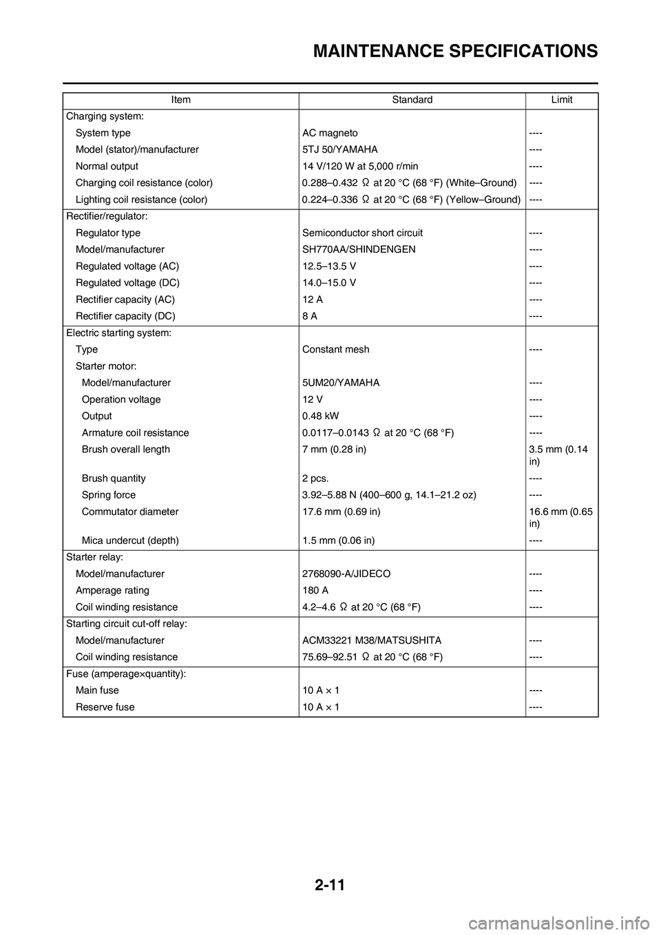
Charging system:
System type AC magneto ----
Model (stator)/manufacturer 5TJ 50/YAMAHA ----
Normal output 14 V/120 W at 5,000 r/min ----
Charging coil resistance (color) 0.288–0.432 Ω at 20 °C (68 °F) (White–Ground) ----
Lighting coil resistance (color) 0.224–0.336 Ω at 20 °C (68 °F) (Yellow–Ground) ----
Rectifier/regulator:
Regulator type Semiconductor short circuit ----
Model/manufacturer SH770AA/SHINDENGEN ----
Regulated voltage (AC) 12.5–13.5 V ----
Regulated voltage (DC) 14.0–15.0 V ----
Rectifier capacity (AC) 12 A ----
Rectifier capacity (DC) 8 A ----
Electric starting system:
Type Constant mesh ----
Starter motor:
Model/manufacturer 5UM20/YAMAHA ----
Operation voltage 12 V ----
Output 0.48 kW ----
Armature coil resistance 0.0117–0.0143 Ω at 20 °C (68 °F) ----
Brush overall length 7 mm (0.28 in) 3.5 mm (0.14
in)
Brush quantity 2 pcs. ----
Spring force 3.92–5.88 N (400–600 g, 14.1–21.2 oz) ----
Commutator diameter 17.6 mm (0.69 in) 16.6 mm (0.65
in)
Mica undercut (depth) 1.5 mm (0.06 in) ----
Starter relay:
Model/manufacturer 2768090-A/JIDECO ----
Amperage rating 180 A ----
Coil winding resistance 4.2–4.6 Ω at 20 °C (68 °F) ----
Starting circuit cut-off relay:
Model/manufacturer ACM33221 M38/MATSUSHITA ----
Coil winding resistance 75.69–92.51 Ω at 20 °C (68 °F) ----
Fuse (amperage×quantity):
Main fuse 10 A × 1 ----
Reserve fuse 10 A × 1 ----Item Standard Limit
Page 43 of 226

2-16
TIGHTENING TORQUES
1. First, tighten the steering ring nut approximately 38 Nm (3.8 m•kg, 27 ft•lb) by using the steering nut wrench, then loosen
the steering ring nut one turn.
2. Retighten the steering ring nut 7 Nm (0.7 m•kg, 5.1 ft•lb).
ELECTRICAL
Tighten the rotor nut to 65 Nm (6.5 m•kg, 47 ft•lb), loosen and retighten the rotor nut to 65 Nm (6.5 m •kg, 47 ft•lb).
△Headlight mounting (left and right) M6 × 1.0 2 7 0.7 5.1
Taillight mounting — 3 1 0.1 0.7
Taillight lead clamp and rear fender — 3 0.5 0.05 0.36
△Catch tank (upper) M6 × 1.0 1 16 1.6 11
△Catch tank (lower) M6 × 1.0 1 7 0.7 5.1
△Footrest bracket and frame M10 × 1.25 4 55 5.5 40
Sidestand mounting M10 × 1.25 1 25 2.5 18Part to be tightened Thread size Q'tyTightening torque
Nm m•kg ft•lb
Part to be tightened Thread size Q'tyTightening torque
Nm m•kg ft•lb
Stator M5 × 0.8 2 7 0.7 5.1
Holder (AC magneto lead) M5× 0.8 2 10 1.0 7.2
Rotor M12 × 1.25 1 Refer to TIP.
Neutral switch M5 × 0.8 2 4 0.4 2.9
Starter motor M6 × 1.0 2 10 1.0 7.2
Starter relay terminal M6 × 1.0 2 4 0.4 2.9
Pickup coil M6 × 1.0 2 10 1.0 7.2
Page 136 of 226

5-38
BALANCER
BALANCER
REMOVING THE BALANCER
Order Part name Q'ty Remarks
Primary driven gear Refer to "CLUTCH" section.
Right crankcase cover Refer to "OIL FILTER ELEMENT AND WA-
TER PUMP" section.
Stator Refer to "CDI MAGNETO" section.
1 Nut (balancer) 1 Refer to removal section.
2 Nut (primary drive gear) 1 Refer to removal section.
3 Nut (balancer shaft driven gear) 1 Refer to removal section.
4 Lock washer 1
5 Balancer 1
6 Straight key 1
7 Conical washer 1
8 Primary drive gear 1
9 Balancer shaft drive gear 1
10 Lock washer 1
11 Balancer shaft driven gear 1
Page 147 of 226

5-49
AC MAGNETO AND STARTER CLUTCH
Tighten the rotor nut to 65 Nm (6.5 m•kg, 47 ft•lb), loosen and retighten the rotor nut to 65 Nm (6.5 m•kg, 47 ft•lb).
12 Woodruff key 1
13 Starter clutch assembly cover 1 Refer to removal section.
14 Starter clutch 1 Refer to removal section.
15 Starter clutch drive gear 1
16 Holder 1
17 Pickup coil 1
18 Stator 1 Order Part name Q'ty Remarks
Page 148 of 226

5-50
AC MAGNETO AND STARTER CLUTCH
REMOVING THE ROTOR
1. Remove:
• Nut (rotor) "1"
• Washer
Use the sheave holder "2".
2. Remove:
• Rotor "1"
Use the rotor puller "2".
REMOVING THE STARTER
CLUTCH
1. Remove:
• Starter clutch assembly cover "1"
Insert a thin screwdriver or the like
under the convexity "a" and remove
the starter clutch assembly cover by
prying it gently to void damage to the
cover.
2. Remove:
• Starter clutch "1"
Using a thin screwdriver or the like,
remove the plate "a" while prying it
upward little by little.
CHECKING THE AC MAGNETO
1. Inspect:
• Rotor inner surface "a"
• Stator outer surface "b"
Damage→Inspect the crankshaft
runout and crankshaft bearing.
If necessary, replace AC magneto
and/or stator.
CHECKING THE WOODRUFF KEY
1. Inspect:
• Woodruff key "1"
Damage→Replace.
CHECKING THE STARTER
CLUTCH
1. Check:
• Starter clutch
Damage/wear→Replace.
2. Check:
• Idle gear
• Idle gear shaft
• Starter clutch drive gear
Pitting/burrs/chips/roughness/
wear→Replace the defective
parts.3. Check:
• Starter clutch operation
a. Install the starter clutch drive gear
"1" onto the starter clutch "2" and
hold the starter clutch.
b. When turning the starter clutch
drive gear counterclockwise "B",
the starter clutch and the starter
clutch drive gear should engage.
If the starter clutch drive gear and
starter clutch do not engage, the
starter clutch is faulty and must be
replaced.
c. When turning the starter clutch
drive gear clockwise "A", it should
turn freely. If the starter clutch
drive gear does not turn freely, the
starter clutch is faulty and must be
replaced.
CHECKING THE TORQUE LIMITER
1. Check:
• Torque limiter
Damage/wear→Replace.
INSTALLING THE AC MAGNETO
AND STARTER CLUTCH
1. Install:
• Stator "1"
• Bolt (stator) "2"
• Pickup coil "3"
• Holder "4"
• Bolt (pickup coil) "5" Sheave holder:
YS-1880-A/90890-
01701
Rotor puller:
YM-04142/90890-04142
Bolt (stator):
7 Nm (0.7 m•kg, 5.1
ft•lb)
Bolt (pickup coil):
10 Nm (1.0 m•kg, 7.2
ft•lb)
Page 149 of 226

5-51
AC MAGNETO AND STARTER CLUTCH
• Pass the AC magneto lead "5" un-
der the pickup coil.
• Pass the AC magneto lead "4" un-
der the holder as shown.
• Take care not to catch the AC mag-
neto lead between crankcase cover
ribs.
• Tighten the bolt (stator) using the
T25 bit.
• Apply the sealant to the grommet of
the AC magneto lead.
2. Install:
• Starter clutch drive gear "1"
Apply the engine oil on the starter
clutch drive gear inner circumference.
3. Install:
• Starter clutch "1"
To rotor "2".
• Install the starter clutch with its
plate side upward.
• While installing the starter clutch,
push in the projections "a" one by
one on the clutch circumference.
• Push in the starter clutch until it hits
the rotor.
4. Install:
• Starter clutch assembly cover "1"
To rotor "2".
Install the starter clutch assembly
cover by fitting its pawls "a" into the
groove "b" in the rotor.
5. Install:
• Woodruff key "1"
• Rotor "2"
• Degrease the contact surfaces of
the tapered portions of the crank-
shaft and rotor.
• When installing the woodruff key,
make sure that its flat surface "a" is
in parallel with the crankshaft center
line "b".
• When installing the rotor, align the
keyway "c" of the rotor with the
woodruff key.
6. Install:
• Washer (rotor)
• Nut (rotor) "1"
Use the sheave holder "2"
Tighten the rotor nut to 65 Nm (6.5
m•kg, 47 ft•lb), loosen and retighten
the rotor nut to 65 Nm (6.5 m•kg, 47
ft•lb).
7. Install:
• Shaft "1"
• Bearing "2"
• Idle gear 2 "3"
Apply the engine oil on the shaft,
bearing and idle gear inner circumfer-
ence.
8. Install:
• Dowel pin
• Gasket [crankcase cover (left)]
• Crankcase cover (left) "1"
• Bolt [crankcase cover (left)]
Tighten the bolts in stage, using a
crisscross pattern.
9. Install:
• Washer "1"
• Torque limiter "2"
• Washer "3"
Apply the engine oil to the shaft and
washers.
YAMAHA Bond No. 1215
(ThreeBond® No. 1215):
90890-85505
Nut (rotor):
65 Nm (6.5 m•kg, 47
ft•lb)
Sheave holder:
YS-1880-A/90890-
01701
Bolt [crankcase cover
(left)]:
10 Nm (1.0 m•kg, 7.2
ft•lb)
Page 155 of 226

5-57
CRANKCASE AND CRANKSHAFT
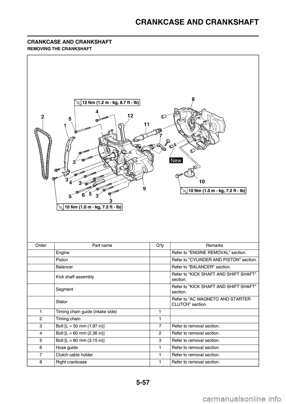
CRANKCASE AND CRANKSHAFT
REMOVING THE CRANKSHAFT
Order Part name Q'ty Remarks
Engine Refer to "ENGINE REMOVAL" section.
Piston Refer to "CYLINDER AND PISTON" section.
Balancer Refer to "BALANCER" section.
Kick shaft assemblyRefer to "KICK SHAFT AND SHIFT SHAFT"
section.
SegmentRefer to "KICK SHAFT AND SHIFT SHAFT"
section.
StatorRefer to "AC MAGNETO AND STARTER
CLUTCH" section.
1 Timing chain guide (intake side) 1
2 Timing chain 1
3 Bolt [L = 50 mm (1.97 in)] 7 Refer to removal section.
4 Bolt [L = 60 mm (2.36 in)] 2 Refer to removal section.
5 Bolt [L = 80 mm (3.15 in)] 3 Refer to removal section.
6 Hose guide 1 Refer to removal section.
7 Clutch cable holder 1 Refer to removal section.
8 Right crankcase 1 Refer to removal section.