Page 7 of 104
TABLE OF CONTENTS
Replacing the headlight bulb ........ 6-32
Replacing the tail/brake light
bulb ........................................... 6-33
Replacing a turn signal light
bulb ........................................... 6-33
Replacing the license plate light
bulb ........................................... 6-34
Replacing an auxiliary light bulb ... 6-34
Supporting the motorcycle ............ 6-35
Front wheel (FZ1-N) ...................... 6-36
Rear wheel (FZ1-N) ....................... 6-37
Troubleshooting ............................ 6-39
Troubleshooting charts ................. 6-40
MOTORCYCLE CARE AND
STORAGE.......................................... 7-1
Matte color caution ......................... 7-1
Care ................................................ 7-1
Storage ...........................................7-3
SPECIFICATIONS ............................. 8-1
CONSUMER INFORMATION............. 9-1
Identification numbers .................... 9-1
U2D1E3E0.book Page 2 Monday, July 14, 2008 3:08 PM
Page 16 of 104
INSTRUMENT AND CONTROL FUNCTIONS
3-2
3
�
Keep other immobilizer system
keys away from the main switch
as they may cause signal inter-ference.
EAU10471
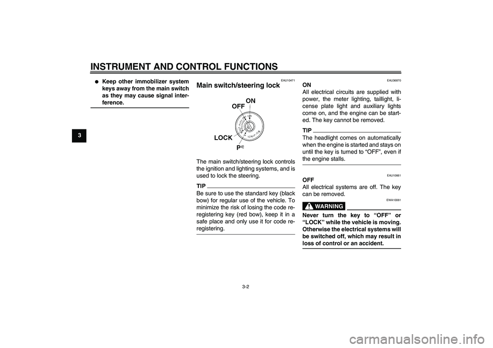
Main switch/steering lock The main switch/steering lock controls
the ignition and lighting systems, and is
used to lock the steering.TIPBe sure to use the standard key (black
bow) for regular use of the vehicle. To
minimize the risk of losing the code re-
registering key (red bow), keep it in a
safe place and only use it for code re-registering.
EAU36870
ON
All electrical circuits are supplied with
power, the meter lighting, taillight, li-
cense plate light and auxiliary lights
come on, and the engine can be start-
ed. The key cannot be removed.TIPThe headlight comes on automatically
when the engine is started and stays on
until the key is turned to “OFF”, even ifthe engine stalls.
EAU10661
OFF
All electrical systems are off. The key
can be removed.
WARNING
EWA10061
Never turn the key to “OFF” or
“LOCK” while the vehicle is moving.
Otherwise the electrical systems will
be switched off, which may result inloss of control or an accident.
U2D1E3E0.book Page 2 Monday, July 14, 2008 3:08 PM
Page 18 of 104

INSTRUMENT AND CONTROL FUNCTIONS
3-4
3
EAU11003
Indicator and warning lights
EAU11030
Turn signal indicator lights“”
and“”
The corresponding indicator light flash-
es when the turn signal switch is
pushed to the left or right.
EAU11060
Neutral indicator light“”
This indicator light comes on when the
transmission is in the neutral position.
EAU11080
High beam indicator light“”
This indicator light comes on when the
high beam of the headlight is switched
on.
EAU11252
Oil level warning light“”
This warning light comes on if the en-
gine oil level is low.
The electrical circuit of the warning light
can be checked by turning the key to
“ON”.
If the warning light does not come on
for a few seconds, then go off, have a
Yamaha dealer check the electrical cir-
cuit.TIP�
Even if the oil level is sufficient, the
warning light may flicker when
riding on a slope or during sudden
acceleration or deceleration, but
this is not a malfunction.
�
This model is also equipped with a
self-diagnosis device for the oil
level detection circuit. If a problem
is detected in the oil level detection
circuit, the following cycle will be
repeated until the malfunction is
corrected: The oil level warning
light will flash ten times, then go off
for 2.5 seconds. If this occurs,
have a Yamaha dealer check thevehicle.
EAU11425
Coolant temperature warning
light“”
This warning light comes on if the en-
gine overheats. If this occurs, stop the
engine immediately and allow the en-
gine to cool.
The electrical circuit of the warning light
can be checked by turning the key to
“ON”.
If the warning light does not come on
for a few seconds, then go off, have a
Yamaha dealer check the electrical cir-
cuit.
1. Left turn signal indicator light“”
2. Right turn signal indicator light“”
3. Neutral indicator light“”
4. High beam indicator light“”
5. Engine trouble warning light“”
6. Oil level warning light“”
7. Coolant temperature warning light“”
8. Anti-lock Brake System (ABS) warning
light“” (for ABS models)
9. Immobilizer system indicator light
ABS
U2D1E3E0.book Page 4 Monday, July 14, 2008 3:08 PM
Page 27 of 104

INSTRUMENT AND CONTROL FUNCTIONS
3-13
3
EAU12347
Handlebar switches LeftRight
EAU12350
Pass switch“”
Press this switch to flash the headlight.
EAU12400
Dimmer switch“/”
Set this switch to“” for the high
beam and to“” for the low beam.
EAU12460
Turn signal switch“/”
To signal a right-hand turn, push this
switch to“”. To signal a left-hand
turn, push this switch to“”. When re-
leased, the switch returns to the centerposition. To cancel the turn signal
lights, push the switch in after it has re-
turned to the center position.
EAU12500
Horn switch“”
Press this switch to sound the horn.
EAU12660
Engine stop switch“/”
Set this switch to“” before starting
the engine. Set this switch to“” to
stop the engine in case of an emergen-
cy, such as when the vehicle overturns
or when the throttle cable is stuck.
EAU12711
Start switch“”
Push this switch to crank the engine
with the starter. See page 5-1 for start-
ing instructions prior to starting the en-
gine.
EAU44710
The engine trouble warning light and
ABS warning light (ABS model only) will
come on when the key is turned to “ON”
and the start switch is pushed, but this
does not indicate a malfunction.
1. Pass switch“”
2. Dimmer switch“/”
3. Turn signal switch“/”
4. Horn switch“”
5. Hazard switch“”
1. Engine stop switch“/”
2. Start switch“”
U2D1E3E0.book Page 13 Monday, July 14, 2008 3:08 PM
Page 54 of 104
PERIODIC MAINTENANCE AND ADJUSTMENT
6-5
6
EAU18680
TIP�
Air filter
This model’s air filter is equipped with a disposable oil-coated paper element, which must not be cleaned with com-
pressed air to avoid damaging it.
The air filter element needs to be replaced more frequently when riding in unusually wet or dusty areas.
�
Hydraulic brake service
Regularly check and, if necessary, correct the brake fluid level.
Every two years replace the internal components of the brake master cylinders and calipers, and change the brake
fluid.
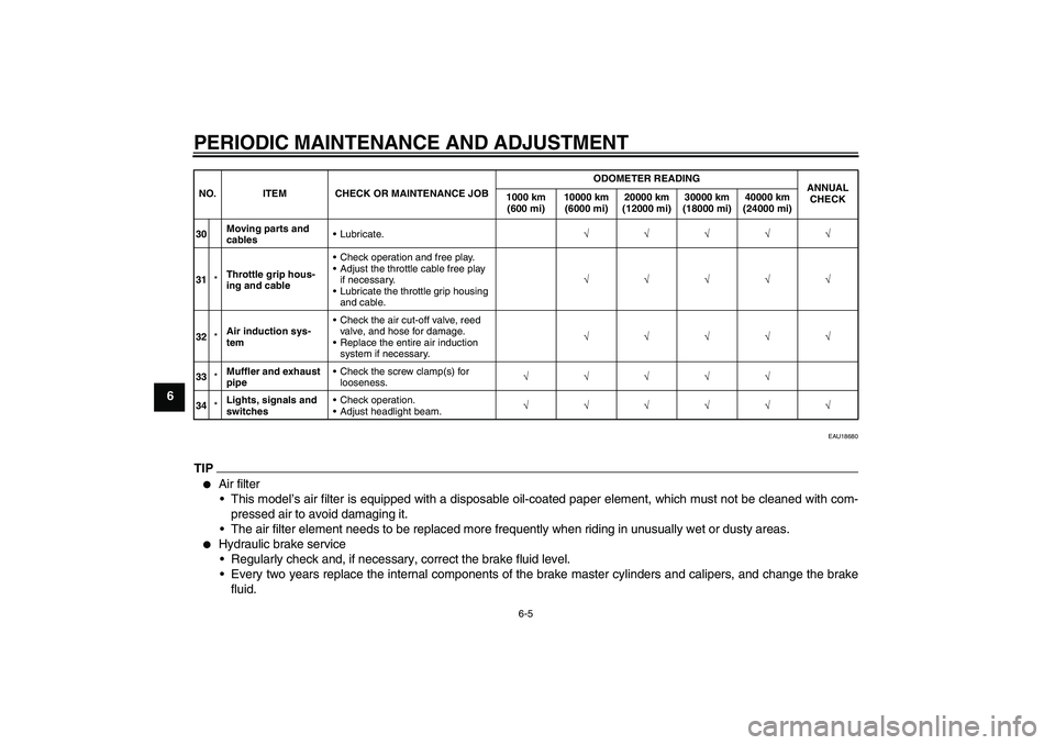
30Moving parts and
cablesLubricate.√√√√√
31*Throttle grip hous-
ing and cableCheck operation and free play.
Adjust the throttle cable free play
if necessary.
Lubricate the throttle grip housing
and cable.√√√√√
32*Air induction sys-
temCheck the air cut-off valve, reed
valve, and hose for damage.
Replace the entire air induction
system if necessary.√√√√√
33*Muffler and exhaust
pipeCheck the screw clamp(s) for
looseness.√√√√√
34*Lights, signals and
switchesCheck operation.
Adjust headlight beam.√√√√√√ NO. ITEM CHECK OR MAINTENANCE JOBODOMETER READING
ANNUAL
CHECK 1000 km
(600 mi)10000 km
(6000 mi)20000 km
(12000 mi)30000 km
(18000 mi)40000 km
(24000 mi)U2D1E3E0.book Page 5 Monday, July 14, 2008 3:08 PM
Page 79 of 104
PERIODIC MAINTENANCE AND ADJUSTMENT
6-30
6
EAU43132
Replacing the fuses The main fuse, the fuel injection system
fuse, and the fuse boxes, which contain
the fuses for the individual circuits, are
located under the rider seat. (See page
3-19.)
FZ1-NFZ1-NA FZ1-N1. Main fuse
2. Fuse box
3. Fuel injection system fuse
4. Fuel injection system spare fuse
1. Main fuse
2. Fuse box
3. Fuel injection system fuse
4. Fuel injection system spare fuse
1. Fuse box
2. Ignition fuse
3. Signaling system fuse
4. Taillight fuse
5. Backup fuse (for odometer, clock and immo-
bilizer system)
6. Right radiator fan fuse
7. Left radiator fan fuse
8. Headlight fuse
9. Spare fuse
U2D1E3E0.book Page 30 Monday, July 14, 2008 3:08 PM
Page 80 of 104
PERIODIC MAINTENANCE AND ADJUSTMENT
6-31
6FZ1-NA
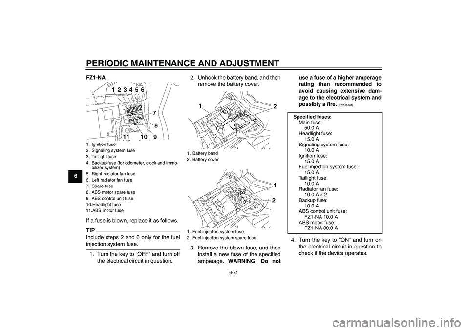
If a fuse is blown, replace it as follows.
TIPInclude steps 2 and 6 only for the fuelinjection system fuse.
1. Turn the key to “OFF” and turn off
the electrical circuit in question.2. Unhook the battery band, and then
remove the battery cover.
3. Remove the blown fuse, and then
install a new fuse of the specified
amperage. WARNING! Do notuse a fuse of a higher amperage
rating than recommended to
avoid causing extensive dam-
age to the electrical system and
possibly a fire.
[EWA15131]
4. Turn the key to “ON” and turn on
the electrical circuit in question to
check if the device operates.
1. Ignition fuse
2. Signaling system fuse
3. Taillight fuse
4. Backup fuse (for odometer, clock and immo-
bilizer system)
5. Right radiator fan fuse
6. Left radiator fan fuse
7. Spare fuse
8. ABS motor spare fuse
9. ABS control unit fuse
10.Headlight fuse
11.ABS motor fuse
1. Battery band
2. Battery cover
1. Fuel injection system fuse
2. Fuel injection system spare fuse
Specified fuses:
Main fuse:
50.0 A
Headlight fuse:
15.0 A
Signaling system fuse:
10.0 A
Ignition fuse:
15.0 A
Fuel injection system fuse:
15.0 A
Taillight fuse:
10.0 A
Radiator fan fuse:
10.0 A × 2
Backup fuse:
10.0 A
ABS control unit fuse:
FZ1-NA 10.0 A
ABS motor fuse:
FZ1-NA 30.0 A
U2D1E3E0.book Page 31 Monday, July 14, 2008 3:08 PM
Page 81 of 104
PERIODIC MAINTENANCE AND ADJUSTMENT
6-32
6 5. If the fuse immediately blows
again, have a Yamaha dealer
check the electrical system.
6. Install the battery cover, and then
hook the battery band onto the
holder.
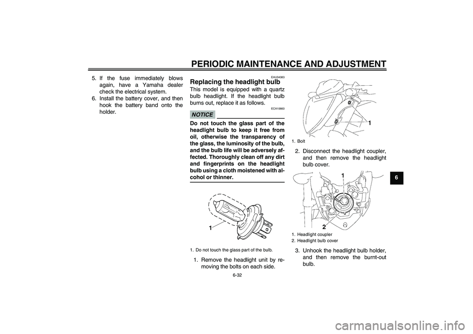
EAU34383
Replacing the headlight bulb This model is equipped with a quartz
bulb headlight. If the headlight bulb
burns out, replace it as follows.NOTICE
ECA10660
Do not touch the glass part of the
headlight bulb to keep it free from
oil, otherwise the transparency of
the glass, the luminosity of the bulb,
and the bulb life will be adversely af-
fected. Thoroughly clean off any dirt
and fingerprints on the headlight
bulb using a cloth moistened with al-cohol or thinner.
1. Remove the headlight unit by re-
moving the bolts on each side.2. Disconnect the headlight coupler,
and then remove the headlight
bulb cover.
3. Unhook the headlight bulb holder,
and then remove the burnt-out
bulb.1. Do not touch the glass part of the bulb.
1. Bolt
1. Headlight coupler
2. Headlight bulb cover
U2D1E3E0.book Page 32 Monday, July 14, 2008 3:08 PM