Page 77 of 104

PERIODIC MAINTENANCE AND ADJUSTMENT
6-28
6
EAU23283
Checking the steering Worn or loose steering bearings may
cause danger. Therefore, the operation
of the steering must be checked as fol-
lows at the intervals specified in the pe-
riodic maintenance and lubrication
chart.
1. Place a stand under the engine to
raise the front wheel off the
ground. (See page 6-35 for more
information.) WARNING! To
avoid injury, securely support
the vehicle so there is no danger
of it falling over.
[EWA10751]
2. Hold the lower ends of the front
fork legs and try to move them for-
ward and backward. If any free
play can be felt, have a Yamaha
dealer check or repair the steering.
EAU23290
Checking the wheel bearings The front and rear wheel bearings must
be checked at the intervals specified in
the periodic maintenance and lubrica-
tion chart. If there is play in the wheel
hub or if the wheel does not turn
smoothly, have a Yamaha dealer check
the wheel bearings.
EAU33654
Battery This model is equipped with a VRLA
(Valve Regulated Lead Acid) battery.
There is no need to check the electro-
lyte or to add distilled water. However,
the battery lead connections need to be
checked and, if necessary, tightened.
WARNING
EWA10760
�
Electrolyte is poisonous and
dangerous since it contains sul-
furic acid, which causes severe
burns. Avoid any contact with
skin, eyes or clothing and al-
ways shield your eyes when
1. Positive battery lead (red)
2. Negative battery lead (black)
3. Battery
U2D1E3E0.book Page 28 Monday, July 14, 2008 3:08 PM
Page 82 of 104

PERIODIC MAINTENANCE AND ADJUSTMENT
6-33
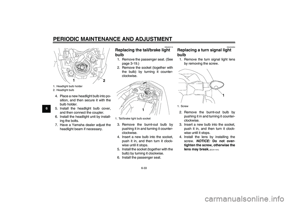
64. Place a new headlight bulb into po-
sition, and then secure it with the
bulb holder.
5. Install the headlight bulb cover,
and then connect the coupler.
6. Install the headlight unit by install-
ing the bolts.
7. Have a Yamaha dealer adjust the
headlight beam if necessary.
EAU24114
Replacing the tail/brake light
bulb 1. Remove the passenger seat. (See
page 3-19.)
2. Remove the socket (together with
the bulb) by turning it counter-
clockwise.
3. Remove the burnt-out bulb by
pushing it in and turning it counter-
clockwise.
4. Insert a new bulb into the socket,
push it in, and then turn it clock-
wise until it stops.
5. Install the socket (together with the
bulb) by turning it clockwise.
6. Install the passenger seat.
EAU24204
Replacing a turn signal light
bulb 1. Remove the turn signal light lens
by removing the screw.
2. Remove the burnt-out bulb by
pushing it in and turning it counter-
clockwise.
3. Insert a new bulb into the socket,
push it in, and then turn it clock-
wise until it stops.
4. Install the lens by installing the
screw. NOTICE: Do not over-
tighten the screw, otherwise the
lens may break.
[ECA11191]
1. Headlight bulb holder
2. Headlight bulb
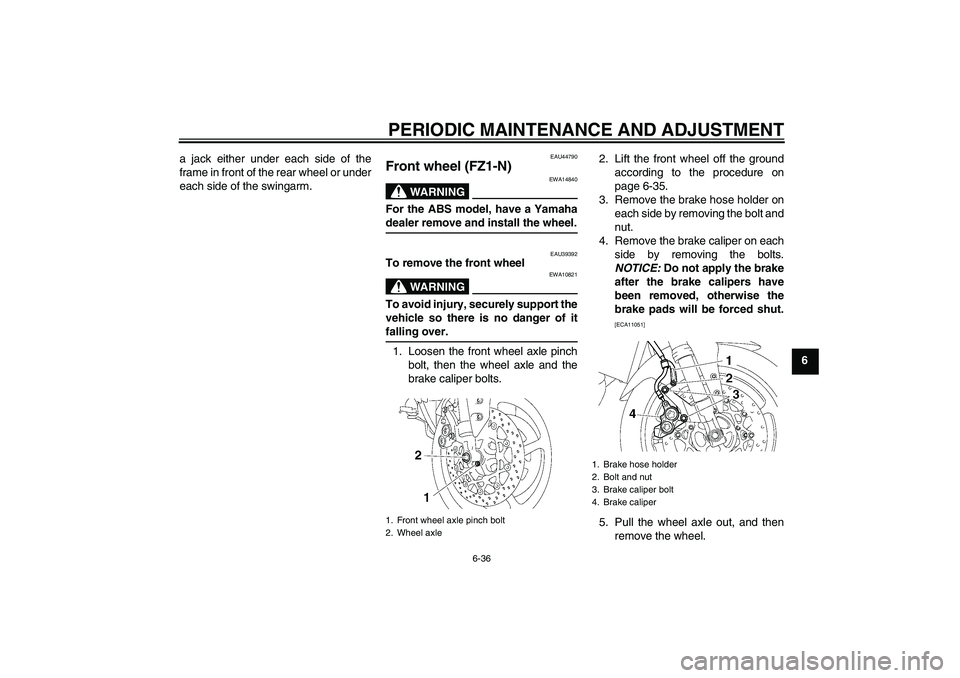
1. Tail/brake light bulb socket
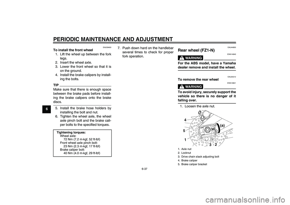
1. Screw
U2D1E3E0.book Page 33 Monday, July 14, 2008 3:08 PM
Page 85 of 104

PERIODIC MAINTENANCE AND ADJUSTMENT
6-36
6 a jack either under each side of the
frame in front of the rear wheel or under
each side of the swingarm.
EAU44790
Front wheel (FZ1-N)
WARNING
EWA14840
For the ABS model, have a Yamahadealer remove and install the wheel.
EAU39392
To remove the front wheel
WARNING
EWA10821
To avoid injury, securely support the
vehicle so there is no danger of itfalling over.
1. Loosen the front wheel axle pinch
bolt, then the wheel axle and the
brake caliper bolts.2. Lift the front wheel off the ground
according to the procedure on
page 6-35.
3. Remove the brake hose holder on
each side by removing the bolt and
nut.
4. Remove the brake caliper on each
side by removing the bolts.
NOTICE: Do not apply the brake
after the brake calipers have
been removed, otherwise the
brake pads will be forced shut.
[ECA11051]
5. Pull the wheel axle out, and then
remove the wheel.
1. Front wheel axle pinch bolt
2. Wheel axle
1. Brake hose holder
2. Bolt and nut
3. Brake caliper bolt
4. Brake caliper
U2D1E3E0.book Page 36 Monday, July 14, 2008 3:08 PM
Page 86 of 104

PERIODIC MAINTENANCE AND ADJUSTMENT
6-37
6
EAU39400
To install the front wheel
1. Lift the wheel up between the fork
legs.
2. Insert the wheel axle.
3. Lower the front wheel so that it is
on the ground.
4. Install the brake calipers by install-
ing the bolts.TIPMake sure that there is enough space
between the brake pads before install-
ing the brake calipers onto the brakediscs.
5. Install the brake hose holders by
installing the bolt and nut.
6. Tighten the wheel axle, the wheel
axle pinch bolt and the brake cali-
per bolts to the specified torques.7. Push down hard on the handlebar
several times to check for proper
fork operation.
EAU44800
Rear wheel (FZ1-N)
WARNING
EWA14840
For the ABS model, have a Yamahadealer remove and install the wheel.
EAU25312
To remove the rear wheel
WARNING
EWA10821
To avoid injury, securely support the
vehicle so there is no danger of itfalling over.
1. Loosen the axle nut.
Tightening torques:
Wheel axle:
72 Nm (7.2 m·kgf, 52 ft·lbf)
Front wheel axle pinch bolt:
23 Nm (2.3 m·kgf, 17 ft·lbf)
Brake caliper bolt:
40 Nm (4.0 m·kgf, 29 ft·lbf)
1. Axle nut
2. Locknut
3. Drive chain slack adjusting bolt
4. Brake caliper
5. Brake caliper bracket
U2D1E3E0.book Page 37 Monday, July 14, 2008 3:08 PM