Page 30 of 106
Features and functions
23
Control system
10
11
12 2
20 34
5
1
9876
17
18
19 16
14 15 13
1Remote control transmitter
2Watertight compartment
3Start switch
4Engine shut-off switch
5Clip
6Engine stop switch
7Engine shut-off cord (lanyard)
8Quick Shift Trim System (QSTS) selector
9QSTS selector lock lever
10Multifunction information center
11Beverage holder
12Rearview mirrors
13Throttle lever
14Shift lever
15Tilt lever
16Glove compartment17Up switch (for cruise assist)
18Down switch (for cruise assist)
19“SET” switch (for cruise assist)
20“NO-WAKE MODE” sw itch
UF2H70E0.book Page 23 Thursday, January 15, 2009 10:49 AM
Page 31 of 106
Features and functions
24
Engine compartment
6 5
7
10 9
8
2143
1Engine cover
2Air filter case
3Water separator
4Fuel tank
5Battery
6Flushing hose connector
7Spark plug cap
8Electrical box
9Engine oil filler cap
10Dipstick
UF2H70E0.book Page 24 Thursday, January 15, 2009 10:49 AM
Page 34 of 106
Features and functions
27
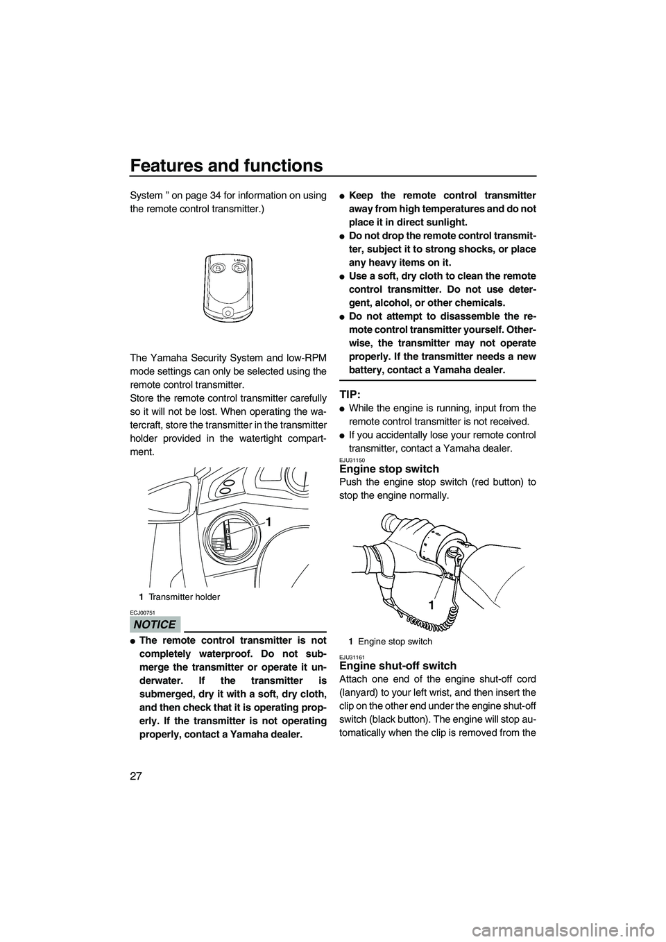
System ” on page 34 for information on using
the remote control transmitter.)
The Yamaha Security System and low-RPM
mode settings can only be selected using the
remote control transmitter.
Store the remote control transmitter carefully
so it will not be lost. When operating the wa-
tercraft, store the transmitter in the transmitter
holder provided in the watertight compart-
ment.
NOTICE
ECJ00751
�The remote control transmitter is not
completely waterproof. Do not sub-
merge the transmitter or operate it un-
derwater. If the transmitter is
submerged, dry it with a soft, dry cloth,
and then check that it is operating prop-
erly. If the transmitter is not operating
properly, contact a Yamaha dealer.
�Keep the remote control transmitter
away from high temperatures and do not
place it in direct sunlight.
�Do not drop the remote control transmit-
ter, subject it to strong shocks, or place
any heavy items on it.
�Use a soft, dry cloth to clean the remote
control transmitter. Do not use deter-
gent, alcohol, or other chemicals.
�Do not attempt to disassemble the re-
mote control transmitter yourself. Other-
wise, the transmitter may not operate
properly. If the transmitter needs a new
battery, contact a Yamaha dealer.
TIP:
�While the engine is running, input from the
remote control transmitter is not received.
�If you accidentally lose your remote control
transmitter, contact a Yamaha dealer.
EJU31150Engine stop switch
Push the engine stop switch (red button) to
stop the engine normally.
EJU31161Engine shut-off switch
Attach one end of the engine shut-off cord
(lanyard) to your left wrist, and then insert the
clip on the other end under the engine shut-off
switch (black button). The engine will stop au-
tomatically when the clip is removed from the
1Transmitter holder
1
1Engine stop switch
1
UF2H70E0.book Page 27 Thursday, January 15, 2009 10:49 AM
Page 35 of 106
Features and functions
28
switch, such as if the operator falls off the wa-
tercraft. Remove the engine shut-off cord
(lanyard) from the watercraft when the engine
is not running to prevent unauthorized use by
children or others.EJU36281Start switch
Push the start switch (green button) to start
the engine.
The engine will not start under any of the fol-
lowing conditions:
�Lock mode of the Yamaha Security System
has been selected. (See page 35 for
Yamaha Security System lock and unlock
mode selection procedures.)
�Clip is removed from the engine shut-off
switch.
�Throttle lever is squeezed.EJU36700Right handlebar switches
1Clip
2Engine shut-off cord (lanyard)
3Engine shut-off switch
1 3
2
1Start switch
1Up switch
2Down switch
3“SET” switch
4“NO-WAKE MODE” sw itch
1
1
2
3
4
UF2H70E0.book Page 28 Thursday, January 15, 2009 10:49 AM
Page 36 of 106
Features and functions
29
EJU36710“SET” switch
Push this switch to activate the cruise assist.
(See page 37 for more information.)
EJU36720Up and down switches
Push these switches to increase or decrease
the engine speed while the cruise assist is op-
erating. (See page 37 for more information.)
EJU36730“NO-WAKE MODE” switch
Push this switch to activate or deactivate the
no-wake mode. (See page 36 for more infor-
mation.)
EJU31210Throttle lever
Squeeze the throttle lever to increase engine
speed.
Release the throttle lever to decrease engine
speed or to return it to the idle position.
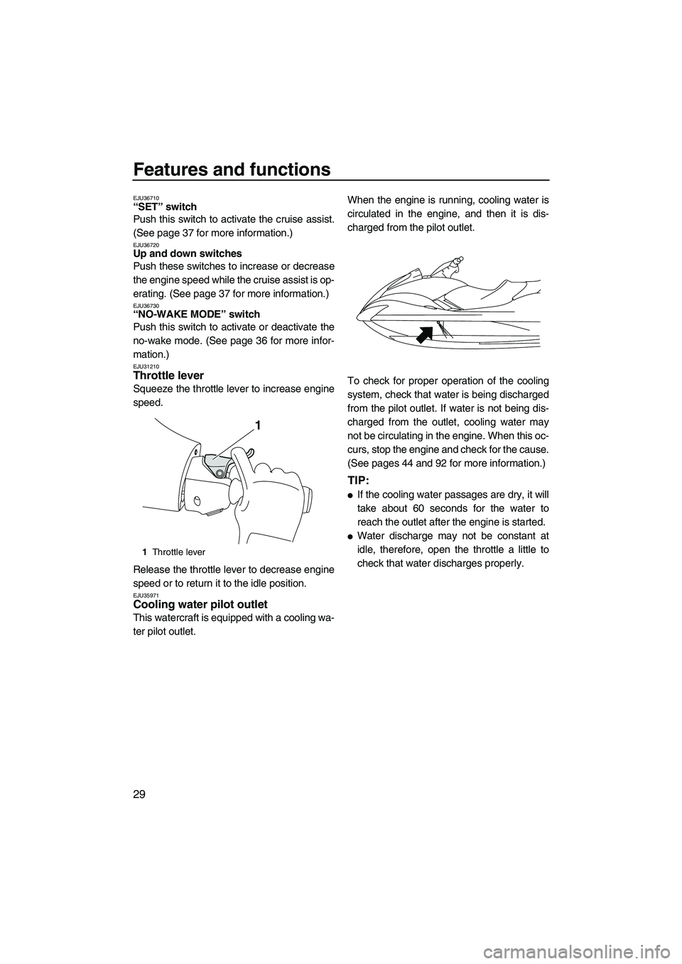
EJU35971Cooling water pilot outlet
This watercraft is equipped with a cooling wa-
ter pilot outlet.When the engine is running, cooling water is
circulated in the engine, and then it is dis-
charged from the pilot outlet.
To check for proper operation of the cooling
system, check that water is being discharged
from the pilot outlet. If water is not being dis-
charged from the outlet, cooling water may
not be circulating in the engine. When this oc-
curs, stop the engine and check for the cause.
(See pages 44 and 92 for more information.)
TIP:
�If the cooling water passages are dry, it will
take about 60 seconds for the water to
reach the outlet after the engine is started.
�Water discharge may not be constant at
idle, therefore, open the throttle a little to
check that water discharges properly.
1Throttle lever
1
UF2H70E0.book Page 29 Thursday, January 15, 2009 10:49 AM
Page 37 of 106
Features and functions
30
EJU31260Steering system
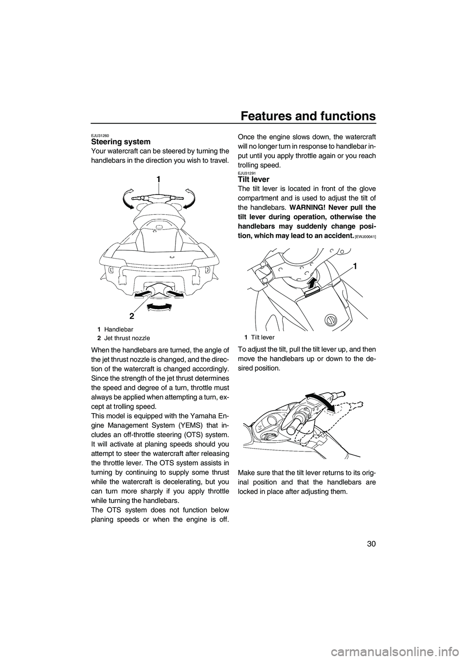
Your watercraft can be steered by turning the
handlebars in the direction you wish to travel.
When the handlebars are turned, the angle of
the jet thrust nozzle is changed, and the direc-
tion of the watercraft is changed accordingly.
Since the strength of the jet thrust determines
the speed and degree of a turn, throttle must
always be applied when attempting a turn, ex-
cept at trolling speed.
This model is equipped with the Yamaha En-
gine Management System (YEMS) that in-
cludes an off-throttle steering (OTS) system.
It will activate at planing speeds should you
attempt to steer the watercraft after releasing
the throttle lever. The OTS system assists in
turning by continuing to supply some thrust
while the watercraft is decelerating, but you
can turn more sharply if you apply throttle
while turning the handlebars.
The OTS system does not function below
planing speeds or when the engine is off.Once the engine slows down, the watercraft
will no longer turn in response to handlebar in-
put until you apply throttle again or you reach
trolling speed.
EJU31291Tilt lever
The tilt lever is located in front of the glove
compartment and is used to adjust the tilt of
the handlebars. WARNING! Never pull the
tilt lever during operation, otherwise the
handlebars may suddenly change posi-
tion, which may lead to an accident.
[EWJ00041]
To adjust the tilt, pull the tilt lever up, and then
move the handlebars up or down to the de-
sired position.
Make sure that the tilt lever returns to its orig-
inal position and that the handlebars are
locked in place after adjusting them.
1Handlebar
2Jet thrust nozzle
1Tilt lever
1
UF2H70E0.book Page 30 Thursday, January 15, 2009 10:49 AM
Page 39 of 106
Features and functions
32
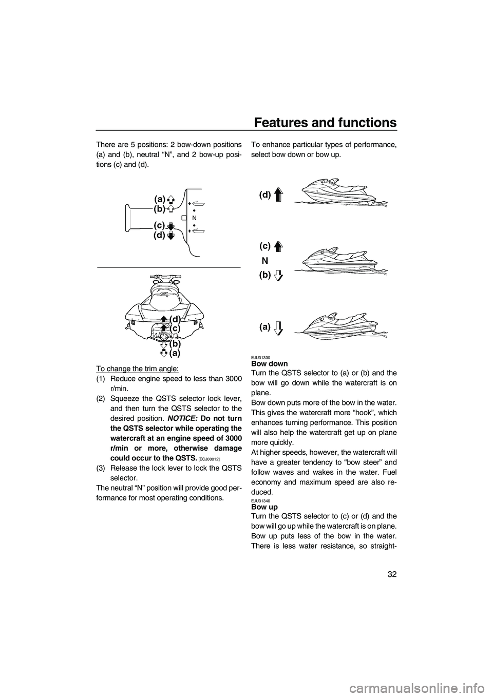
There are 5 positions: 2 bow-down positions
(a) and (b), neutral “N”, and 2 bow-up posi-
tions (c) and (d).
To change the trim angle:
(1) Reduce engine speed to less than 3000
r/min.
(2) Squeeze the QSTS selector lock lever,
and then turn the QSTS selector to the
desired position. NOTICE: Do not turn
the QSTS selector while operating the
watercraft at an engine speed of 3000
r/min or more, otherwise damage
could occur to the QSTS.
[ECJ00012]
(3) Release the lock lever to lock the QSTS
selector.
The neutral “N” position will provide good per-
formance for most operating conditions.To enhance particular types of performance,
select bow down or bow up.
EJU31330Bow down
Turn the QSTS selector to (a) or (b) and the
bow will go down while the watercraft is on
plane.
Bow down puts more of the bow in the water.
This gives the watercraft more “hook”, which
enhances turning performance. This position
will also help the watercraft get up on plane
more quickly.
At higher speeds, however, the watercraft will
have a greater tendency to “bow steer” and
follow waves and wakes in the water. Fuel
economy and maximum speed are also re-
duced.
EJU31340Bow up
Turn the QSTS selector to (c) or (d) and the
bow will go up while the watercraft is on plane.
Bow up puts less of the bow in the water.
There is less water resistance, so straight-
UF2H70E0.book Page 32 Thursday, January 15, 2009 10:49 AM
Page 41 of 106
Features and functions
34
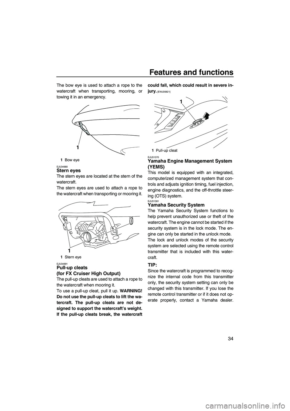
The bow eye is used to attach a rope to the
watercraft when transporting, mooring, or
towing it in an emergency.
EJU34880Stern eyes
The stern eyes are located at the stern of the
watercraft.
The stern eyes are used to attach a rope to
the watercraft when transporting or mooring it.
EJU34891Pull-up cleats
(for FX Cruiser High Output)
The pull-up cleats are used to attach a rope to
the watercraft when mooring it.
To use a pull-up cleat, pull it up. WARNING!
Do not use the pull-up cleats to lift the wa-
tercraft. The pull-up cleats are not de-
signed to support the watercraft’s weight.
If the pull-up cleats break, the watercraftcould fall, which could result in severe in-
jury.
[EWJ00821]
EJU31370
Yamaha Engine Management System
(YEMS)
This model is equipped with an integrated,
computerized management system that con-
trols and adjusts ignition timing, fuel injection,
engine diagnostics, and the off-throttle steer-
ing (OTS) system.
EJU31381Yamaha Security System
The Yamaha Security System functions to
help prevent unauthorized use or theft of the
watercraft. The engine cannot be started if the
security system is in the lock mode. The en-
gine can only be started in the unlock mode.
The lock and unlock modes of the security
system are selected using the remote control
transmitter that is included with this water-
craft.
TIP:
Since the watercraft is programmed to recog-
nize the internal code from this transmitter
only, the security system setting can only be
changed with this transmitter. If you lose the
remote control transmitter or if it does not op-
erate properly, contact a Yamaha dealer.
1Bow eye
1Stern eye
1
1Pull-up cleat
1
UF2H70E0.book Page 34 Thursday, January 15, 2009 10:49 AM