2009 SUBARU OUTBACK fuel cap
[x] Cancel search: fuel capPage 4 of 447
2
Chapter 12: Specifications
This chapter informs you about the dimen-
sions and capacities of your SUBARU.
Chapter 13: Consumer information and
Reporting safety defects
This chapter informs you about Tire
information, Uniform tire quality grading
standards and Reporting safety defects.
Chapter 14: Index
This is an alphabetical listing of all that’sin
this manual. You can use it to quickly find
something you want to read. & Safety warnings
You will find a number of WARNINGs,
CAUTIONs and NOTEs in this manual.
These safety warnings alert you to poten-
tial hazards that could result in injury to
you or others.
Please read these safety warnings as well
as all other portions of this manual care-
fully in order to gain a better understand-
ing of how to use your SUBARU vehicle
safely.
WARNING
A WARNING indicates a situation in
which serious injury or death could
result if the warning is ignored.
CAUTION
A CAUTION indicates a situation in
which injury or damage to your
vehicle, or both, could result if the
caution is ignored.
NOTE
A NOTE gives information or sugges-
tions how to make better use of yourvehicle. & Safety symbol
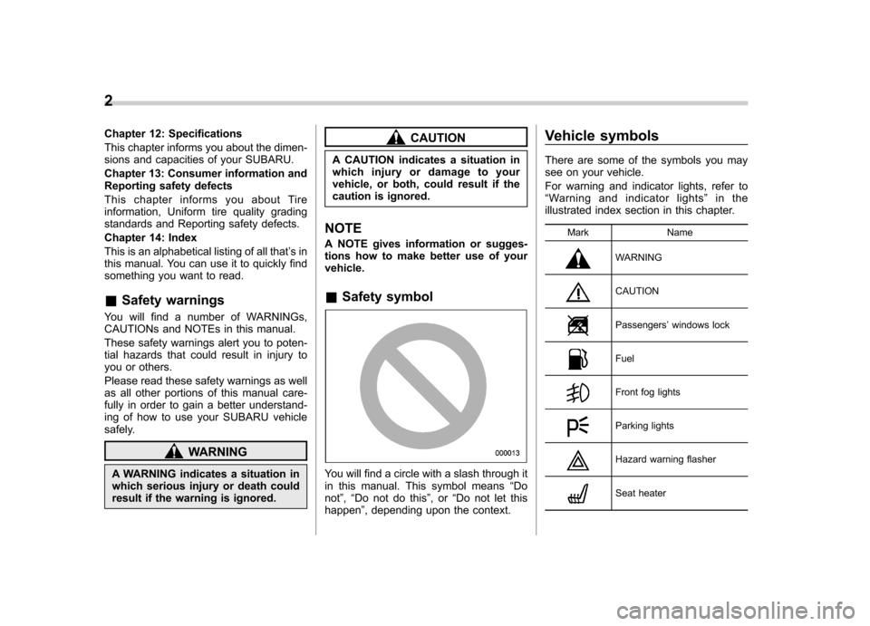
You will find a circle with a slash through it
in this manual. This symbol means “Do
not ”, “Do not do this ”,or “Do not let this
happen ”, depending upon the context. Vehicle symbols
There are some of the symbols you may
see on your vehicle.
For warning and indicator lights, refer to “
Warning and indicator lights ”in the
illustrated index section in this chapter.
Mark Name
WARNING
CAUTION
Passengers ’windows lock
Fuel
Front fog lights
Parking lights
Hazard warning flasher
Seat heater
Page 13 of 447
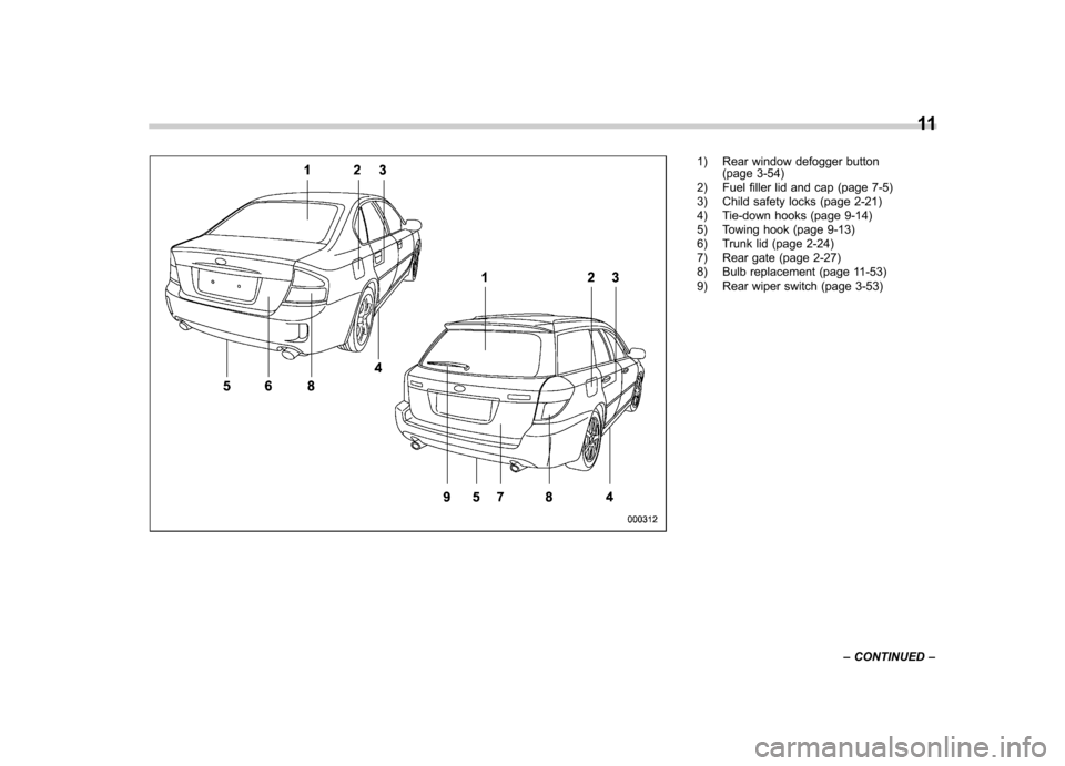
1) Rear window defogger button(page 3-54)
2) Fuel filler lid and cap (page 7-5)
3) Child safety locks (page 2-21)
4) Tie-down hooks (page 9-14)
5) Towing hook (page 9-13)
6) Trunk lid (page 2-24)
7) Rear gate (page 2-27)
8) Bulb replacement (page 11-53)
9) Rear wiper switch (page 3-53) 11
– CONTINUED –
Page 155 of 447

3-32Instruments and controls
control system checked and re-
paired as necessary could cause
serious damage, which may not be
covered by your vehicle ’s warranty.
If this light illuminates steadily or blinks
while the engine is running, it may indicate
that there is a problem or potential
problem somewhere in the emission con-
trol system. ! If the light illuminates steadily
If the light illuminates steadily while driving
or does not go out after the engine starts,
an emission control system malfunction
has been detected.
You should have your vehicle checked by
an authorized SUBARU dealer immedi-
ately. NOTE
This light also illuminates when the fuel
filler cap is not tightened until it clicks.
If you have recently refueled your vehicle,
the cause of the CHECK ENGINE warning
light/malfunction indicator lamp coming on
could be a loose or missing fuel filler cap.
Remove the cap and retighten it until it
clicks. Make sure nothing is interfering
with the sealing of the cap. Tightening the
cap will not make the CHECK ENGINE
warning light/malfunction indicator lamp turn off immediately. It may take several
driving trips. If the light does not go out,
take your vehicle to your authorized
SUBARU dealer immediately. !
If the light is blinking
If the light is blinking while driving, an
engine misfire condition has been de-
tected which may damage the emission
control system.
To prevent serious damage to the emis-
sion control system, you should conform
to the following instructions. . Reduce vehicle speed.
. Avoid hard acceleration.
. Avoid steep uphill grades.
. Reduce the amount of cargo, if possi-
ble.. Stop towing a trailer as soon as
possible.
The CHECK ENGINE warning light/mal-
function indicator lamp may stop blinking
and illuminate steadily after several driv-
ing trips. You should have your vehicle
checked by an authorized SUBARU deal-
er immediately.
& Charge warning light
If this light illuminates when the engine is
running, it may indicate that the charging
system is not working properly. If the light illuminates while driving or does
not go out after the engine starts, stop the
engine at the first safe opportunity and
check the alternator belt. If the belt is
loose, broken or if the belt is in good
condition but the light remains on, contact
your nearest SUBARU dealer immedi-
ately. &
Oil pressure warning light
CAUTION
Do not operate the engine with the
oil pressure warning light on. This
may cause serious engine damage.
If this light illuminates when the engine is
running, it may indicate that the engine oil
pressure is low and the lubricating system
is not working properly.
If the light illuminates while driving or does
not go out after the engine starts, stop the
engine at the first safe opportunity and
check the engine oil level. If the oil level is
low, add oil immediately. If the engine oil is
at the proper level but the light remains on,
contact your nearest SUBARU dealer
immediately.
Page 247 of 447
Fuel...................................................................... 7-3
Fuel requirements ............................................... 7-3
Fuel filler lid and cap ........................................... 7-5
State emission testing (U.S. only) ...................... 7-7
Preparing to drive ............................................... 7-8
Starting the engine .............................................. 7-9
Manual transmission vehicle ................................ 7-9
Automatic transmission vehicle .......................... 7-10
Stopping the engine ........................................... 7-11
Remote engine start system (dealer option) ................................................. 7-11
Starting your vehicle .......................................... 7-12
Remote start safety features ............................... 7-12
Entering the vehicle while it is running via remote start ................................................................. 7-12
Entering the vehicle following remote engine start shutdown ......................................................... 7-12
Pre-heating or pre-cooling the interior of the vehicle ............................................................. 7-13
Service mode ..................................................... 7-13
Remote transmitter programming and programmable feature option ............................ 7-13
System maintenance .......................................... 7-14
Manual transmission –5 speeds ...................... 7-15
Shifting speeds .................................................. 7-15
Driving tips ........................................................ 7-16
Manual transmission –6 speeds (2.5GT
spec.B) ............................................................. 7-17
Selecting reverse gear ........................................ 7-17
Shifting speeds .................................................. 7-17
Driving tips ........................................................ 7-18 Automatic transmission
–4-speed ................... 7-18
Selector lever .................................................... 7-19
Selector lever reverse inhibiting function ............ 7-20
Selection of manual mode .................................. 7-21
Maximum speeds ............................................... 7-22
Driving tips ........................................................ 7-23
SPORT mode ..................................................... 7-23
Shift lock release ............................................... 7-24
Automatic transmission –5-speed ................... 7-24
Selector lever .................................................... 7-25
Selector lever reverse inhibiting function ............ 7-26
Selection of manual mode .................................. 7-27
Maximum speeds ............................................... 7-29
Driving tips ........................................................ 7-29
Shift lock release ............................................... 7-30
SI-DRIVE (turbo and 3.0 L models) .................. 7-31
Intelligent (I) mode ............................................. 7-31
Sport (S) mode .................................................. 7-32
Sport Sharp (S#) mode. ...................................... 7-32
SI-DRIVE selector .............................................. 7-32
SI-DRIVE Sport Sharp (S#) switch ...................... 7-33
Rear viscous limited slip differential (LSD) (if equipped) .................................................... 7-33
Power steering ................................................... 7-34
Braking ............................................................... 7-34
Braking tips ....................................................... 7-34
Brake system .................................................... 7-34
Disc brake pad wear warning indicators ............. 7-35
ABS (Anti-lock Brake System) .......................... 7-35
ABS system self-check ...................................... 7-35
Starting and operating
7
Page 251 of 447
.Fuel system damage or driveability
problems which result from the use of
improper fuel are not covered under the
SUBARU Limited Warranty. & Fuel filler lid and cap
! Refueling
Only one person should be involved in
refueling. Do not allow others to approach
the area of the vehicle near the fuel filler
pipe while refueling is in progress.
Be sure to observe any other precautions
that are posted at the service station.
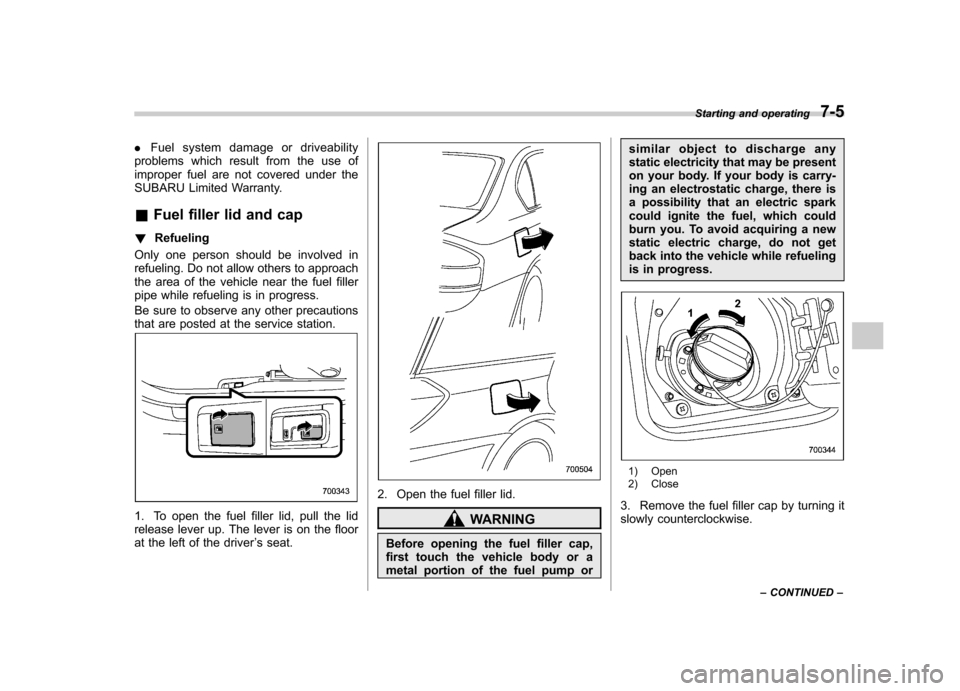
1. To open the fuel filler lid, pull the lid
release lever up. The lever is on the floor
at the left of the driver ’s seat.
2. Open the fuel filler lid.
WARNING
Before opening the fuel filler cap,
first touch the vehicle body or a
metal portion of the fuel pump or similar object to discharge any
static electricity that may be present
on your body. If your body is carry-
ing an electrostatic charge, there is
a possibility that an electric spark
could ignite the fuel, which could
burn you. To avoid acquiring a new
static electric charge, do not get
back into the vehicle while refueling
is in progress.
1) Open
2) Close
3. Remove the fuel filler cap by turning it
slowly counterclockwise. Starting and operating
7-5
– CONTINUED –
Page 252 of 447
7-6Starting and operating
WARNING
. Gasoline vapor is highly flam-
mable. Before refueling, always
first stop the engine and close all
vehicle doors and windows.
Make sure that there are no
lighted cigarettes, open flames
or electrical sparks in the adja-
cent area. Refueling must be
performed outside. Quickly wipe
up any spilled fuel.
. When opening the cap, grasp it
firmly and turn it slowly to the
left. Do not remove the cap
quickly. Fuel may be under pres-
sure and spray out of the fuel
filler neck, especially in hot
weather. If you hear a hissing
sound while you are removing
the cap, wait for the sound to
stop and then slowly open the
cap to prevent fuel from spraying
out and creating a fire hazard.
. When refueling, insert the fuel
nozzle securely into the fuel filler
pipe. If the nozzle is lifted or not
fully inserted, its automatic stop-
ping mechanism may not func-
tion, causing fuel to overflow the
tank and creating a fire hazard.
. Stop refueling when the auto- matic stop mechanism on the
fuel nozzle activates. If you con-
tinue to add fuel, temperature
changes or other conditions
may cause fuel to overflow from
the tank and create a fire hazard.
4. Stop filling the tank after the fuel filler
pump automatically turns off. Do not add
any more fuel.
CAUTION
Make sure that the cap is tightened
until it clicks to prevent fuel spillage
in the event of an accident.
5. Put the cap back on, turn it clockwise
until you hear a clicking noise. Be certain
not to catch the tether under the cap whiletightening.
6. Close the fuel filler lid completely. If
you spill any fuel on the painted surface,
rinse it off immediately. Otherwise, the
painted surface could be damaged. NOTE
.
You will see the “”sign in the fuel
gauge. This indicates that the fuel filler
door (lid) is located on the right side of
the vehicle.. If the fuel filler cap is not tightened
until it clicks or if the tether is caught
under the cap, the CHECK ENGINE
warning light/malfunction indicator
lamp may illuminate. Refer to the“ Warning and indicator lights ”section
located in chapter 3.
CAUTION
. Never add any cleaning agents to
the fuel tank. The addition of a
cleaning agent may cause da-
Page 253 of 447
mage to the fuel system.
. After refueling, turn the cap to the
right until it clicks to ensure that
it is fully tightened. If the cap is
not securely tightened, fuel may
leak out while the vehicle is being
driven or fuel spillage could
occur in the event of an accident,
creating a fire hazard.
. Do not let fuel spill on the exterior
surfaces of the vehicle. Because
fuel may damage the paint, be
sure to wipe off any spilled fuel
quickly. Paint damage caused by
spilled fuel is not covered under
the SUBARU Limited Warranty.
. Always use a genuine SUBARU
fuel filler cap. If you use the
wrong cap, it may not fit, and
your fuel tank and emission con-
trol system may be damaged. It
could also lead to fuel spillage
and a fire.
. Immediately put fuel in the tank
whenever the low fuel warning
light illuminates. Engine misfires
as a result of an empty tank
could cause damage to the en-gine. State emission testing (U.S. only)
WARNING
Testing of an All-Wheel Drive vehicle
must NEVER be performed on a
single two-wheel dynamometer. At-
tempting to do so will result in
uncontrolled vehicle movement and
may cause an accident or injuries to
persons nearby.
CAUTION
Resultant vehicle damage due to
improper testing is not covered
under the SUBARU Limited War-
ranty and is the responsibility of
the state inspection program or its
contractors or licensees.
At state inspection time, remember to
tell your inspection or service station in
advance not to place your SUBARU
AWD vehicle on a two-wheel dynam-
ometer. Otherwise, serious transmis-
sion damage will result.
Some states have started using dynam-
ometers in their state inspection programs in order to meet their obligation under
federal law to implement stricter vehicle
emission standards to reduce air pollution
from vehicles. A dynamometer is a tread-
mill or roller-like testing device that allows
your vehicle
’s wheels to turn while the
vehicle remains in one place. Depending
on the severity of a state ’s air pollution
problems, the states must adopt either a“ basic ”or “enhanced ”vehicle emission
inspection test. Normally, a portion of the
basic emission test consists of an emis-
sion inspector inserting an analyzer probe
into the exhaust pipe of an idling vehicle
for a short period of time. States with more
severe air pollution problems are required
to adopt an enhanced vehicle emission
test. This test simulates actual driving
conditions on a dynamometer and permits
more accurate measurement of tailpipe
emitted pollution than the basic emissiontest.
The U.S. Environmental Protection
Agency (EPA) and states using two-wheel
dynamometers in their emission testing
programs have EXEMPTEDSUBARU
AWD vehicles from the portion of the
testing program that involves a two-wheel
dynamometer.
There are some states that use four-wheel
dynamometers in their testing programs.
When properly used, that equipment will Starting and operating
7-7
– CONTINUED –
Page 297 of 447

New vehicle break-in driving–the first
1,000 miles (1,600 km) ..................................... 8-2
Fuel economy hints ............................................ 8-2
Engine exhaust gas (carbon monoxide) ............ 8-3
Catalytic converter .............................................. 8-3
Periodic inspections ........................................... 8-4
Driving in foreign countries ............................... 8-5
Driving tips for AWD vehicles ............................ 8-5
Off road driving ................................................... 8-6
All AWD models except OUTBACK ...................... 8-6
OUTBACK ........................................................... 8-6
Winter driving ...................................................... 8-8
Operation during cold weather ............................. 8-8
Driving on snowy and icy roads .......................... 8-9
Corrosion protection .......................................... 8-10
Snow tires ......................................................... 8-11 Tire chains
........................................................ 8-13
Rocking the vehicle ........................................... 8-13
Loading your vehicle ......................................... 8-13
Vehicle capacity weight ...................................... 8-14
GVWR and GAWR (Gross Vehicle Weight Rating and Gross Axle Weight Rating) ........................ 8-15
Roof rail and crossbar (if equipped) ................... 8-15
Trailer hitch (if equipped) .................................. 8-19
Connecting a trailer ........................................... 8-20
When you do not tow a trailer .. .......................... 8-21
Trailer towing ..................................................... 8-21
Warranties and maintenance .............................. 8-21
Maximum load limits .......................................... 8-22
Trailer hitches .................................................... 8-25
Connecting a trailer ........................................... 8-26
Trailer towing tips .............................................. 8-27Driving tips
8