2009 SUBARU OUTBACK brake
[x] Cancel search: brakePage 16 of 447

14
1) Parking brake lever (page 7-44)
2) Gear shift lever (MT) (page 7-15/page 7-17)
3) Selector lever (AT) (page 7-19/ page 7-25)
4) Information display (page 3-41)
5) Clock (page 3-41)
6) Dashboard storage compartment (page 6-5)
7) Navigation system (Refer to the Owner ’s
Manual supplement for the navigation system.)
8) Glove box (page 6-5)
9) Hazard warning flasher switch (page 3-5)
10) Audio (page 5-1)
11) Climate control (page 4-1)
12) Pocket (page 6-8)
13) Accessory power outlet (page 6-9)
14) Tilt/telescopic steering wheel (page 3-59)
15) SI-DRIVE selector (page 7-32)
16) Cup holder (page 6-8)
Page 23 of 447

&Warning and indicator lights
Mark Name Page
Seatbelt warning light 3-29
Front passenger ’s
seatbelt warning light 3-29
SRS airbag system
warning light3-30
CHECK ENGINE
warning light/Malfunc-
tion indicator lamp3-31
Charge warning light 3-32
Oil pressure warning light
3-32
AT OIL TEMP warning
light (AT models)3-33
/ABS warning light 3-34
/Brake system warning light
3-35
Door open warning light3-36Mark Name Page
/Low fuel warning light 3-36
All-Wheel Drive warn-
ing light (AT models)
3-36
Vehicle Dynamics
Control operation indi-
cator light (if equipped)3-37
Vehicle Dynamics
Control warning light (if
equipped)/Vehicle Dy-
namics Control OFF
indicator light (if
equipped)3-37
Security indicator light 3-38
Turn signal indicator lights
3-40
High beam indicator light
3-40
Front fog light indicator
light (if equipped)3-40
Cruise control indicator light3-40
Cruise control set indi-
cator light3-40Mark Name Page
Headlight indicator light 3-40
Low tire pressure
warning light
(U.S.-spec. models)
3-33
/Front passenger
’s
frontal airbag ON indi-
cator light 1-48/
3-31
/Front passenger ’s
frontal airbag OFF in-
dicator light 1-48/
3-31
SPORT mode indicator
light (4-speed AT mod- els) 3-38
Shift-up indicator light
(MT models with
SI-DRIVE)3-38
S# PREP indicator light
(vehicle with
SI-DRIVE)3-3921
– CONTINUED –
Page 31 of 447

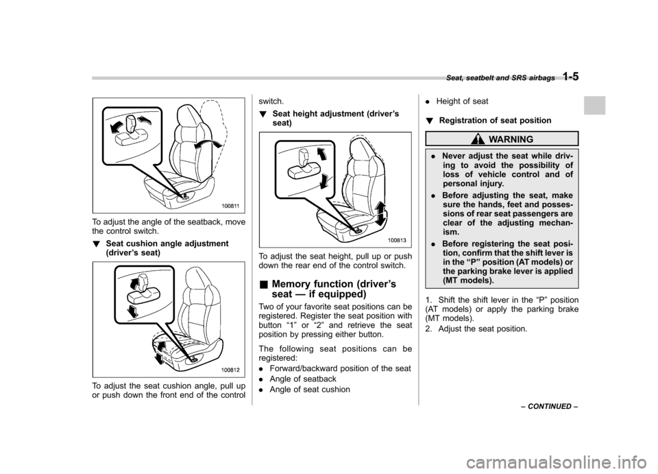
To adjust the angle of the seatback, move
the control switch. !Seat cushion angle adjustment (driver ’s seat)
To adjust the seat cushion angle, pull up
or push down the front end of the control switch. !
Seat height adjustment (driver ’s
seat)
To adjust the seat height, pull up or push
down the rear end of the control switch. & Memory function (driver ’s
seat —if equipped)
Two of your favorite seat positions can be
registered. Register the seat position withbutton “1 ” or “2 ” and retrieve the seat
position by pressing either button.
The following seat positions can be registered: . Forward/backward position of the seat
. Angle of seatback
. Angle of seat cushion .
Height of seat
! Registration of seat position
WARNING
. Never adjust the seat while driv-
ing to avoid the possibility of
loss of vehicle control and of
personal injury.
. Before adjusting the seat, make
sure the hands, feet and posses-
sions of rear seat passengers are
clear of the adjusting mechan-ism.
. Before registering the seat posi-
tion, confirm that the shift lever is
in the “P ” position (AT models) or
the parking brake lever is applied
(MT models).
1. Shift the shift lever in the “P ” position
(AT models) or apply the parking brake
(MT models).
2. Adjust the seat position. Seat, seatbelt and SRS airbags
1-5
– CONTINUED –
Page 32 of 447

1-6Seat, seatbelt and SRS airbags
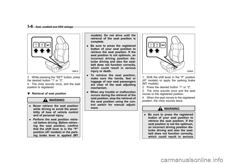
3. While pressing the “SET ”button, press
the desired button “1 ” or “2 ”.
4. The chirp sounds once, and the seat
position is registered. ! Retrieval of seat position
WARNING
. Never retrieve the seat position
while driving to avoid the possi-
bility of loss of vehicle control
and of personal injury.
. Perform the seat position retrie-
val before driving. Before retriev-
ing the seat position, confirm
that the shift lever is in the “P ”
position (AT models) or the park-
ing brake lever is applied (MT models). Do not drive until the
retrieval of the seat position iscomplete.
. Be sure to press the registered
button of your seat position to
retrieve the seat position. If the
seat position is not optimum, an
incorrect driving position dis-
turbs driving and also the seat-
belt does not function correctly,
which could result in serious
injury or death.
. To retrieve the seat position,
make sure the hands, feet or
luggage of rear seat passengers
are clear of the seat adjustingmechanism.
. When any trouble or malfunction
occurs during the retrieval of the
seat position, stop the retrieval of
the seat position using the con-
trol switch for manual adjust-ment.
1. Shift the shift lever in the “P ” position
(AT models) or apply the parking brake
(MT models).
2. Press the desired button “1 ” or “2 ”.
3. The chirp sounds once and the seat
moves to the registered position.
4. When the seat moves to the registered
position, the chirp sounds twice.
WARNING
. Be sure to press the registered
button of your seat position to
retrieve the seat position. If the
seat position is not the optimum,
an incorrect driving position dis-
turbs driving and also the seat-
belt does not function correctly,
which could result in serious
Page 124 of 447

Ignition switch..................................................... 3-3
LOCK .................................................................. 3-3
Acc..................................................................... 3-4
ON...................................................................... 3-4
START ................................................................ 3-4
Key reminder chime ............................................ 3-5
Ignition switch light ............................................. 3-5
Hazard warning flasher ....................................... 3-5
Meters and gauges (vehicle with SI-DRIVE) ...... 3-5
Combination meter illumination ........................... 3-5
Speedometer ....................................................... 3-6
Tachometer ......................................................... 3-6
Fuel gauge .......................................................... 3-6
Temperature gauge ............................................. 3-7
ECO gauge ......................................................... 3-8
Multi-information display (vehicle with SI-DRIVE) .................................... 3-9
Display ............................................................... 3-9
Operation switch ................................................. 3-9
Odometer and trip meter .................................... 3-10
Current and average fuel consumption ............... 3-11
Outside temperature and journey time ................ 3-12
Driving range on remaining fuel .......................... 3-14
Clock (vehicle with genuine SUBARU navigation system) ............................................................ 3-15
SI-DRIVE display ................................................ 3-15
Meter settings .................................................... 3-15
Warning messages and driver ’s information ........ 3-20
Meters and gauges (vehicle without SI-DRIVE) .............................. 3-24
Combination meter illumination .......................... 3-24 Canceling the function for meter/gauge needle
movement upon turning on the ignition switch ............................................................. 3-24
Speedometer ..................................................... 3-24
Odometer .......................................................... 3-25
Double trip meter ............................................... 3-25
Tachometer ....................................................... 3-26
Fuel gauge ........................................................ 3-26
Temperature gauge ............................................ 3-27
Warning and indicator lights ............................. 3-28
Seatbelt warning light and chime ....................... 3-29
SRS airbag system warning light ........................ 3-30
Front passenger ’s frontal airbag ON and OFF
indicators ........................................................ 3-31
CHECK ENGINE warning light/Malfunction indicator lamp ................................................. 3-31
Charge warning light .......................................... 3-32
Oil pressure warning light .................................. 3-32
AT OIL TEMP warning light (AT models) .............. 3-33
Low tire pressure warning light (U.S.-spec. models) ........................................................... 3-33
ABS warning light .............................................. 3-34
Brake system warning light ................................ 3-35
Low fuel warning light ....................................... 3-36
Door open warning light .................................... 3-36
All-Wheel Drive warning light (AT models) ..... ..... 3-36
Vehicle Dynamics Control operation indicator light (if equipped). ............................................ 3-37
Vehicle Dynamics Control warning light (if equipped)/Vehicle Dynamics Control OFF
indicator light (if equipped) .............................. 3-37
Security indicator light ....................................... 3-38
Instruments and controls
3
Page 145 of 447

3-22Instruments and controls
Warning messages Details
Door open warning
When any of the doors, the rear gate (Station wagon) or the trunk lid
(Sedan) is not fully closed, it is indicated by the corresponding part of the
door light.
Always make sure this warning message is out before you start to drive.
The display shows the interruptive warning message for 3 seconds.
Parking brake warning
This warning message illuminates with the parking brake applied while the
ignition switch is in the“ON ”position. It goes out when the parking brake is
fully released.
The display shows the interruptive warning message for 3 seconds and
then returns to its original display. The interruptive warning message will be
displayed again after 20 seconds.
Run mode change system warning
This warning message indicates a malfunction of the “SI-DRIVE mode ”
change. If this warning message is shown on the display, contact your
nearest SUBARU dealer and have the SI-DRIVE mode system inspected.
The display shows the interruptive warning message for 3 seconds.
Engine coolant temperature warning
When the engine coolant temperature reaches 248 8F (120 8C), this warning
message is indicated. If this warning message is displayed, refer to the “ Engine overheating
”section in chapter 9 for details the necessary measures.
The display shows the interruptive warning message for 3 seconds.
Page 151 of 447

3-28Instruments and controls
accordance with the outside temperature
and driving conditions.
We recommend that you drive moderately
until the pointer of the temperature gauge
reaches near the middle of the range.
Engine operation is optimum with the
engine coolant at this temperature range.
Also, high revving operation while the
engine is not sufficiently warmed up
should be avoided.
CAUTION
If the pointer exceeds the normal
operating range, safely stop the
vehicle as soon as possible.
Refer to “In case of emergency ”in
chapter 9. Warning and indicator lights
Several of the warning and indicator lights
illuminate momentarily and then go out
when the ignition switch is initially turned
to the
“ON ”position. This permits check-
ing the operation of the bulbs.
Apply the parking brake and turn the
ignition switch to the “ON ”position. The
following lights illuminate:: Seatbelt warning light (The seatbelt warning light goes out
only when the driver fastens theseatbelt.)
: Front passenger ’s seatbelt warning
light
(The seatbelt warning light goes out
only when the front seat passenger
fastens the seatbelt.)
: SRS airbag system warning light
: CHECK ENGINE warning light/Mal- function indicator lamp
: Charge warning light
: Oil pressure warning light
: AT OIL TEMP warning light(AT models)
/: ABS warning light
: Vehicle Dynamics Control operation
indicator light (if equipped)
: Vehicle Dynamics Control warning light(if equipped)/Vehicle Dynamics Control
OFF indicator light (if equipped)
/: Brake system warning light
: All-Wheel Drive warning light (AT models)
: Low tire pressure warning light(U.S.-spec. models)
: SPORT mode indicator light
(4-speed AT models)
/: Front passenger ’s frontal airbag
ON indicator light
/: Front passenger ’s frontal airbag
OFF indicator light
or: Low fuel warning light
or: Door open warning light
: Cruise control indicator light
: Cruise control set indicator light
: Shift-up indicator light (MT models with SI-DRIVE)
: S# PREP indicator light(vehicle with SI-DRIVE)
Page 157 of 447

3-34Instruments and controls
WARNING
If this light does not illuminate
briefly after the ignition switch is
turned ON or the light illuminates
steadily after blinking for approxi-
mately one minute, you should have
your Tire Pressure Monitoring Sys-
tem checked at a SUBARU dealer as
soon as possible.
If this light illuminates while driving,
never brake suddenly and keep
driving straight ahead while gradu-
ally reducing speed. Then slowly
pull off the road to a safe place.
Otherwise an accident involving
serious vehicle damage and serious
personal injury could occur.
If this light still illuminates while
driving after adjusting the tire pres-
sure, a tire may have significant
damage and a fast leak that causes
the tire to lose air rapidly. If you have
a flat tire, replace it with a spare tire
as soon as possible.
When a spare tire is mounted or a
wheel rim is replaced without the
original pressure sensor/transmitter
being transferred, the Low tire pres-
sure warning light will illuminates
steadily after blinking for approxi-
mately one minute. This indicates the TPMS is unable to monitor all
four road wheels. Contact your
SUBARU dealer as soon as possible
for tire and sensor replacement and/
or system resetting. If the light
illuminates steadily after blinking
for approximately one minute,
promptly contact a SUBARU dealer
to have the system inspected.
CAUTION
The tire pressure monitoring system
is NOT a substitute for manually
checking tire pressure. The tire
pressure should be checked peri-
odically (at least monthly) using a
tire gauge. After any change to tire
pressure(s), the tire pressure mon-
itoring system will not re-check tire
inflation pressures until the vehicle
is first driven more than 20 mph (32
km/h). After adjusting the tire pres-
sures, increase the vehicle speed to
at least 20 mph (32 km/h) to start the
TPMS re-checking of the tire infla-
tion pressures. If the tire pressures
are now above the severe low
pressure threshold, the low tire
pressure warning light should turn
off a few minutes later. Therefore, be
sure to install the specified size for the front and rear tires.
& ABS warning light
The ABS warning light illuminates when
the ignition switch is turned to the “ON ”
position and goes out after approximately
2 seconds.
This is an indication that the ABS system
is working properly.
CAUTION
If the warning light behaves as
follows, the ABS system may not
work properly.
When the warning light is on, the
ABS function shuts down; however,
the conventional brake system con-
tinues to operate normally. . The warning light does not illu-
minate when the ignition switch
is turned to the “ON ”position.
. The warning light illuminates
when the ignition switch is
turned to the “ON ”position, but
it does not go out even when the
vehicle speed exceeds approxi-
mately 8 mph (12 km/h).
. The warning light illuminates dur-
ing driving.