2009 SUBARU OUTBACK door lock
[x] Cancel search: door lockPage 148 of 447

&Odometer
This meter displays the odometer when
the ignition switch is in the “LOCK ”, “Acc ”
or “ON ”position.
The odometer shows the total distance
that the vehicle has been driven.
If you press the trip knob when the ignition
switch is in the “LOCK ”position, the
odometer/trip meter will light up. If you
do not press the trip knob within 10
seconds of illumination of the odometer/
trip meter, the odometer/trip meter will go
off.
Also, if you open and close the driver ’s
door within 10 seconds of illumination of
the odometer/trip meter, the odometer/trip
meter will go off. &
Double trip meterThis meter displays the two trip meters
when the ignition switch is in the “LOCK ”,
“ Acc ”or “ON ”position.
The trip meter shows the distance that the
vehicle has been driven since you last set
it to zero.
To change the mode indication, briefly
push the knob.
Each press of the knob changes the mode
indication alternately.
To set the trip meter to zero, select the A
trip or B trip meter by pushing the knob
and keep the knob pushed for more than 2seconds.
If you press the trip knob when the ignition
switch is in the “LOCK ”position, the
odometer/trip meter will light up. It is
possible to switch between the A trip
meter and B trip meter indications while
the odometer/trip meter is lit up. If you do
not press the trip knob within 10 seconds
of illumination of the odometer/trip meter,
the odometer/trip meter will go off.
Also, if you open and close the driver ’s
door within 10 seconds of illumination of
the odometer/trip meter, the odometer/trip
meter will go off.
CAUTION
To ensure safety, do not attempt to
change the function of the indicator
during driving, as an accident couldresult.
NOTE
If the connection between the combina-
tion meter and battery is broken for any
reason such as vehicle maintenance or
fuse replacement, the data recorded on
the trip meter will be lost. Instruments and controls
3-25
– CONTINUED –
Page 161 of 447

3-38Instruments and controls
may be considered normal. . The warning light illuminates right
after the engine is started but goes out
immediately, remaining off.. The warning light illuminates after
engine startup and goes off while the
vehicle is subsequently being driven.. The warning light illuminates during
driving, but it goes out immediately and
remains off. ! Vehicle Dynamics Control OFF in-
dicator light
. It illuminates when the Vehicle Dy-
namics Control OFF switch is pressed. . It also illuminates when the Vehicle
Dynamics Control system is deactivated. NOTE . The light may stay on for a while
after the engine has been started,
especially in cold weather. This does
not indicate the existence of a problem.
The light should go out as soon as the
engine has warmed up.. The indicator light illuminates when
the engine has developed a problem
and the CHECK ENGINE warning light/
malfunction indicator lamp is on.
The Vehicle Dynamics Control system is
probably faulty under the following condi-
tion. Have your vehicle checked at a SUBARU dealer as soon as possible. .
The light does not go out even after the
lapse of several minutes (the engine has
warmed up) after the engine has started.
& Security indicator light
This indicator light shows the status of the
alarm system. It also indicates operation
of the immobilizer system. !Alarm system
It blinks to show the driver the operational
status of the alarm system. For detailed
information, refer to the “Alarm system ”
section in chapter 2. ! Immobilizer system
This light blinks approximately 60 seconds
after the ignition switch is turned from“ ON ”position to the “Acc ”or “LOCK ”
position or immediately after the key is
pulled out. Refer to the “Door locks ”
section in chapter 2.
If the indicator light does not flash, it may
indicate that immobilizer system may be
faulty. Contact your nearest SUBARU
dealer immediately.
In the event that an unauthorized key (for
example, an unauthorized duplicate) is
used, the security indicator light illumi-nates. &
SPORT mode indicator
light (4-speed AT mod-els)
This light illuminates when the ignition
switch is turned to the “ON ”position and
goes out after the engine has started.
When the selector lever is moved to the
manual gate, the SPORT mode is se-
lected and the indicator light illuminates.
Refer to the “Automatic transmission –4-
speed ”section in chapter 7.
& Shift-up indicator light
(MT models with SI- DRIVE)
When the ignition switch is turned to the “ON ”position, the indicator light illumi-
nates for 3 seconds, and then turns off.
While selecting the Intelligent (I) mode of
SI-DRIVE, this indicator light illuminates
and informs the upshift timing to the driver
for fuel-efficient driving.
Page 191 of 447

!Temperature control dial
Driver ’s side
Passenger ’s side
It is possible to make separate tempera-
ture settings for the driver ’s side and passenger
’s side. Each temperature
setting is shown on the display. With the
dial set at your desired temperature, the
system automatically adjusts the tempera-
ture of air supplied from the outlets such
that the desired temperature is achieved
and maintained.
If the dial is turned fully counterclockwise,
the system gives maximum cooling per-
formance. If the dial is turned fully clock-
wise, the system gives maximum heatingperformance. !
– Defroster button
To defrost or dehumidify the windshield
and front door windows, push the defros-
ter button “
”. When the “”button is
pushed, outside air is drawn into the
passenger compartment, air flow is direc-
ted towards the windshield and front door windows, and the indicator light on the
button illuminates.
After eliminating the fogging from the
windshield, return the climate control
system to the AUTO mode by pushingthe
“AUTO ”button or turn off by pushing
the “OFF ”button.
Alternatively, push the “
”button again
to return the system to the setting that was
selected before you activated the defros-
ter. ! Fan speed control button
The fan speed control button has 6
different fan speed positions.
The fan speed is shown by the display. Climate control
4-9
– CONTINUED –
Page 242 of 447

HomeLink®Wireless Control
System (if equipped)
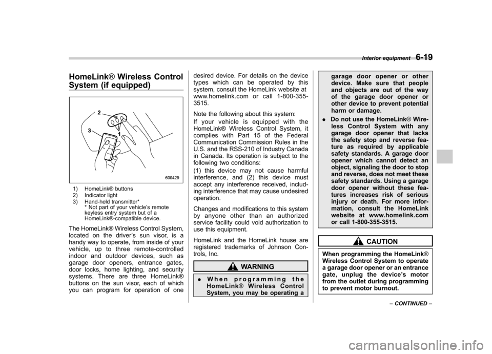
1) HomeLink® buttons
2) Indicator light
3) Hand-held transmitter* * Not part of your vehicle ’s remote
keyless entry system but of a
HomeLink®-compatible device.
The HomeLink® Wireless Control System,
located on the driver ’s sun visor, is a
handy way to operate, from inside of your
vehicle, up to three remote-controlled
indoor and outdoor devices, such as
garage door openers, entrance gates,
door locks, home lighting, and security
systems. There are three HomeLink®
buttons on the sun visor, each of which
you can program for operation of one desired device. For details on the device
types which can be operated by this
system, consult the HomeLink website at
www.homelink.com or call 1-800-355-3515.
Note the following about this system:
Ifyourvehicleisequippedwiththe
HomeLink® Wireless Control System, it
complies with Part 15 of the Federal
Communication Commission Rules in the
U.S. and the RSS-210 of Industry Canada
in Canada. Its operation is subject to the
following two conditions:
(1) this device may not cause harmful
interference, and (2) this device must
accept any interference received, includ-
ing interference that may cause undesiredoperation.
Changes and modifications to this system
by anyone other than an authorized
service facility could void authorization to
use this equipment.
HomeLink and the HomeLink house are
registered trademarks of Johnson Con-
trols, Inc.
WARNING
. When programming the
HomeLink ®Wireless Control
System, you may be operating a garage door opener or other
device. Make sure that people
and objects are out of the way
of the garage door opener or
other device to prevent potential
harm or damage.
. Do not use the HomeLink ®Wire-
less Control System with any
garage door opener that lacks
the safety stop and reverse fea-
ture as required by applicable
safety standards. A garage door
opener which cannot detect an
object, signaling the door to stop
and reverse, does not meet these
safety standards. Using a garage
door opener without these fea-
tures increases risk of serious
injury or death. For more infor-
mation, consult the HomeLink
website at www.homelink.com
or call 1-800-355-3515.
CAUTION
When programming the HomeLink ®
Wireless Control System to operate
a garage door opener or an entrance
gate, unplug the device ’s motor
from the outlet during programming
to prevent motor burnout. Interior equipment
6-19
– CONTINUED –
Page 245 of 447

6-22Interior equipment
trol System and your garage door opener
should activate when the HomeLink®
button is pressed. & Programming for entrance
gates and garage door open-
ers in Canada
1. Unplug the motor of the entrance gate
or garage door opener from the outlet.
2. Press and hold the two outside buttons
until the HomeLink® indicator light begins
to flash (after 20 seconds). Release bothbuttons. NOTE
If any of the HomeLink ®buttons are
already programmed for other devices,
skip step 2 because it clears the memory of all three buttons.
3. Hold the end of the entrance gate
’s/
garage door opener ’s hand-held transmit-
ter between 1 and 3 inches (25 and 76
mm) away from the HomeLink® buttons
on the driver ’s sun visor, keeping the
indicator light in view.
4. Press and hold the desired
HomeLink® button.
5. Press and release ( “cycle ”) the hand-
held transmitter button every 2 seconds
until step 6 is complete.
6. When the indicator light flashes slowly
and then rapidly after several seconds,
release both buttons.
7. Plug the motor of the entrance gate/
garage door opener to the outlet.
8. Test your entrance gate/garage door opener by pressing the programmed
HomeLink® button. &
Programming other devices
To program other devices such as door
locks, home lighting and security systems,
contact HomeLink at www.homelink.com
or call 1-800-355-3515. & Operating the HomeLink ®
Wireless Control System
Once programmed, the HomeLink® Wire-
less Control System can be used to
remote-control the devices to which its
buttons are programmed. To activate a
device, simply press the appropriate but-
ton. The indicator light illuminates, indicat-
ing that the signal is being transmitted. & Reprogramming a single HomeLink ®button
1. Press and hold the HomeLink® button
you wish to reprogram. DO NOT release
the button until step 4 has been com-pleted.
2. When the HomeLink® indicator light
begins to flash slowly (after 20 seconds),
position the hand-held transmitter of the
device for which you wish to program the
button at 1 to 3 inches (25 to 76 mm) away
from the HomeLink® button surface.
Page 252 of 447

7-6Starting and operating
WARNING
. Gasoline vapor is highly flam-
mable. Before refueling, always
first stop the engine and close all
vehicle doors and windows.
Make sure that there are no
lighted cigarettes, open flames
or electrical sparks in the adja-
cent area. Refueling must be
performed outside. Quickly wipe
up any spilled fuel.
. When opening the cap, grasp it
firmly and turn it slowly to the
left. Do not remove the cap
quickly. Fuel may be under pres-
sure and spray out of the fuel
filler neck, especially in hot
weather. If you hear a hissing
sound while you are removing
the cap, wait for the sound to
stop and then slowly open the
cap to prevent fuel from spraying
out and creating a fire hazard.
. When refueling, insert the fuel
nozzle securely into the fuel filler
pipe. If the nozzle is lifted or not
fully inserted, its automatic stop-
ping mechanism may not func-
tion, causing fuel to overflow the
tank and creating a fire hazard.
. Stop refueling when the auto- matic stop mechanism on the
fuel nozzle activates. If you con-
tinue to add fuel, temperature
changes or other conditions
may cause fuel to overflow from
the tank and create a fire hazard.
4. Stop filling the tank after the fuel filler
pump automatically turns off. Do not add
any more fuel.
CAUTION
Make sure that the cap is tightened
until it clicks to prevent fuel spillage
in the event of an accident.
5. Put the cap back on, turn it clockwise
until you hear a clicking noise. Be certain
not to catch the tether under the cap whiletightening.
6. Close the fuel filler lid completely. If
you spill any fuel on the painted surface,
rinse it off immediately. Otherwise, the
painted surface could be damaged. NOTE
.
You will see the “”sign in the fuel
gauge. This indicates that the fuel filler
door (lid) is located on the right side of
the vehicle.. If the fuel filler cap is not tightened
until it clicks or if the tether is caught
under the cap, the CHECK ENGINE
warning light/malfunction indicator
lamp may illuminate. Refer to the“ Warning and indicator lights ”section
located in chapter 3.
CAUTION
. Never add any cleaning agents to
the fuel tank. The addition of a
cleaning agent may cause da-
Page 258 of 447

7-12Starting and operating
&Starting your vehicle
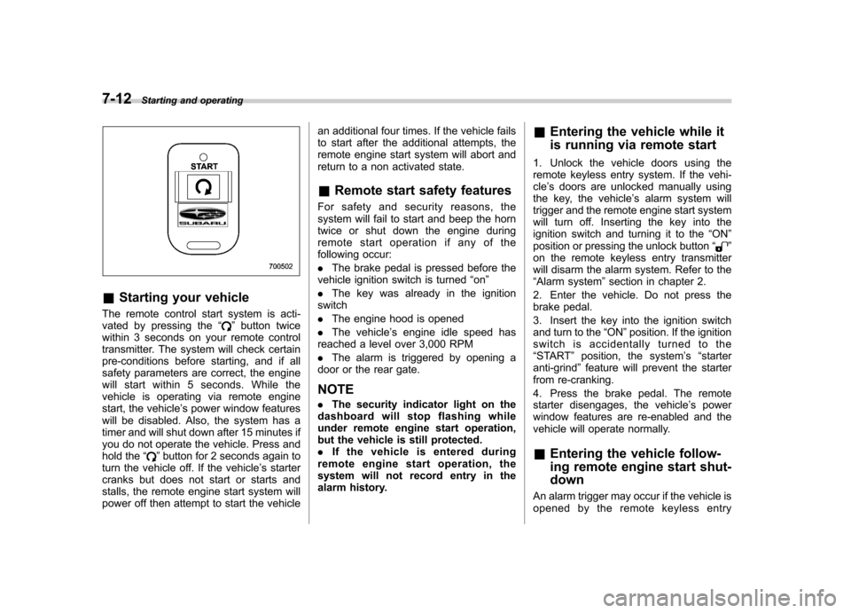
The remote control start system is acti-
vated by pressing the “
”button twice
within 3 seconds on your remote control
transmitter. The system will check certain
pre-conditions before starting, and if all
safety parameters are correct, the engine
will start within 5 seconds. While the
vehicle is operating via remote engine
start, the vehicle ’s power window features
will be disabled. Also, the system has a
timer and will shut down after 15 minutes if
you do not operate the vehicle. Press and
hold the “
”button for 2 seconds again to
turn the vehicle off. If the vehicle ’s starter
cranks but does not start or starts and
stalls, the remote engine start system will
power off then attempt to start the vehicle an additional four times. If the vehicle fails
to start after the additional attempts, the
remote engine start system will abort and
return to a non activated state. &
Remote start safety features
For safety and security reasons, the
system will fail to start and beep the horn
twice or shut down the engine during
remote start operation if any of the
following occur: . The brake pedal is pressed before the
vehicle ignition switch is turned “on ”
. The key was already in the ignition
switch. The engine hood is opened
. The vehicle ’s engine idle speed has
reached a level over 3,000 RPM. The alarm is triggered by opening a
door or the rear gate. NOTE . The security indicator light on the
dashboard will stop flashing while
under remote engine start operation,
but the vehicle is still protected.. If the vehicle is entered during
remote engine start operation, the
system will not record entry in the
alarm history. &
Entering the vehicle while it
is running via remote start
1. Unlock the vehicle doors using the
remote keyless entry system. If the vehi-cle ’s doors are unlocked manually using
the key, the vehicle ’s alarm system will
trigger and the remote engine start system
will turn off. Inserting the key into the
ignition switch and turning it to the “ON ”
position or pressing the unlock button “
”
on the remote keyless entry transmitter
will disarm the alarm system. Refer to the“ Alarm system ”section in chapter 2.
2. Enter the vehicle. Do not press the
brake pedal.
3. Insert the key into the ignition switch
and turn to the “ON ”position. If the ignition
switch is accidentally turned to the“ START ”position, the system ’s “starter
anti-grind ”feature will prevent the starter
from re-cranking.
4. Press the brake pedal. The remote
starter disengages, the vehicle ’s power
window features are re-enabled and the
vehicle will operate normally.
& Entering the vehicle follow-
ing remote engine start shut-down
An alarm trigger may occur if the vehicle is
opened by the remote keyless entry
Page 302 of 447

8-6Driving tips
vehicle and may affect ride, handling,
braking, speedometer/odometer calibra-
tion, and clearance between the body
and tires. It also may be dangerous and
lead to loss of vehicle control. .If you use a temporary spare tire to
replace a flat tire, be sure to use the
original temporary spare tire stored in the
vehicle. Using other sizes may result in
severe mechanical damage to the drive
train of your vehicle. . Always check the cold tire pressure
before starting to drive. The recom-
mended tire pressure is provided on the
tire placard, which is located under the
door latch on the driver ’s side.
. Tire chains should always be placed on
the front wheels only. . There are some precautions that you
must observe when towing your vehicle.
For detail information, refer to the “Towing ”
section in chapter 9. Off road driving
WARNING
. Always maintain a safe driving
speed according to the road and
weather conditions in order to
avoid having an accident on a
sharp turn, during sudden brak-
ing or under other similar condi-tions.
. Always use the utmost care in
driving –overconfidence be-
cause you are driving an All-
Wheel Drive vehicle could easily
lead to a serious accident.
& All AWD models except OUTBACK
Your AWD vehicle is neither a conven-
tional off-road vehicle nor an all terrain
vehicle. It is a passenger car designed
primarily for on-road use. The AWD
feature gives it some limited off-road
capabilities in situations in which driving
surfaces a relatively level, obstruction-free
and otherwise similar to on-road driving
conditions. Operating it under other than
those conditions could subject the vehicle
to excessive stress which might result in damage not eligible for repair under
warranty. If you do take your SUBARU
off road, you should review the common
sense precautions in the next section
(applicable to the OUTBACK) for general
guidance. But please keep in mind that
your vehicle
’s off-road capabilities are
more limited than those of the OUTBACK.
Never attempt to drive through pools and
puddles, or roads flooded with water.
Water entering the engine air intake or
the exhaust pipe or water splashing onto
electrical parts may damage your vehicle
and may cause it to stall. & OUTBACK
Because of the AWD feature and higher
ground clearance, your SUBARU can be
driven on ordinary roads or off-road. But
please keep in mind that an AWD
SUBARU is a passenger car and is
neither a conventional off-road vehicle
nor an all-terrain vehicle. If you do take
your SUBARU off-road, certain common
sense precautions such as those in the
following list should be taken: . Make certain that you and all of your
passengers are wearing seatbelts. . Carry some emergency equipment,
such as a towing rope or chain, a shovel,
wheel blocks, first aid kit and cell phone or
citizens band radio.