2009 SUBARU LEGACY warning
[x] Cancel search: warningPage 388 of 447

11-38Maintenance and service
&Wheel balance
Each wheel was correctly balanced when
your vehicle was new, but the wheels will
become unbalanced as the tires become
worn during use. Wheel imbalance causes
the steering wheel to vibrate slightly at
certain vehicle speeds and detracts from
the vehicle ’s straight-line stability. It can
also cause steering and suspension sys-
tem problems and abnormal tire wear. If
you suspect that the wheels are not
correctly balanced, have them checked
and adjusted by your SUBARU dealer.
Also have them adjusted after tire repairs
and after tire rotation. NOTE
Loss of correct wheel alignment*
causes the tires to wear on one side
and reduces the vehicle ’s running
stability. Contact your SUBARU dealer
if you notice abnormal tire wear.
*: The suspension system is designed to hold
each wheel at a certain alignment (relative to
the other wheels and to the road) for optimum
straight-line stability and cornering perfor- mance. &
Wear indicators
1) New tread
2) Worn tread
3) Tread wear indicator
Each tire incorporates a tread wear
indicator, which becomes visible when
the depth of the tread grooves decreases
to 0.063 in (1.6 mm). A tire must be
replaced when the tread wear indicator
appears as a solid band across the tread.
WARNING
When a tire ’s tread wear indicator
becomes visible, the tire is worn
beyond the acceptable limit and
must be replaced immediately. With
a tire in this condition, driving at
high speeds in wet weather can cause the vehicle to hydroplane.
The resulting loss of vehicle control
can lead to an accident.
NOTE
For safety, inspect the tire tread reg-
ularly and replace the tires before their
tread wear indicators become visible. & Tire rotation direction markExample of tire rotation direction mark
1) Front
If the tire has a rotation direction specifica-
tion, the tire rotation direction mark is
placed on its sidewall.
When you install a tire that has the tire
rotation direction mark, install the tire with
Page 390 of 447
11-40Maintenance and service
WARNING
. All four tires must be the same in
terms of manufacturer, brand
(tread pattern), construction, de-
gree of wear, speed symbol, load
index and size. Mixing tires of
different types, sizes or degrees
of wear can result in damage to
the vehicle ’s power train. Use of
different types or sizes of tires
can also dangerously reduce
controllability and braking per-
formance and can lead to anaccident.
. Use only radial tires. Do not use
radial tires together with belted
bias tires and/or bias-ply tires.
Doing so can dangerously re-
duce controllability, resulting in
an accident. &
Wheel replacement
When replacing wheels due, for example,
to damage, make sure the replacement
wheels match the specifications of the
wheels that are fitted as standard equip-
ment. Replacement wheels are available
from SUBARU dealers.
WARNING
Use only those wheels that are
specified for your vehicle. Wheels
not meeting specifications could
interfere with brake caliper opera-
tion and may cause the tires to rub
against the wheel well housing dur-
ing turns. The resulting loss of
vehicle control could lead to anaccident. Aluminum wheels
Aluminum wheels can be scratched and
damaged easily. Handle them carefully to
maintain their appearance, performance,
and safety. .
When any of the wheels is removed
and replaced for tire rotation or to change
a flat, always check the tightness of the
wheel nuts after driving approximately 600
miles (1,000 km). If any nut is loose,
tighten it to the specified torque. . Never apply oil to the threaded parts,
wheel nuts, or tapered surface of the wheel. . Never let the wheel rub against sharp
protrusions or curbs.. Be sure to fit tire chains on uniformly
and completely around the tire, otherwise
the chains may scratch the wheel. . When wheel nuts, balance weights, or
the center cap is replaced, be sure to
replace them with genuine SUBARU parts
designed for aluminum wheels.
Page 396 of 447
11-46Maintenance and service
ends. If the rubber is not retained properly,
the wiper may scratch the rear windowglass.
5. Install the wiper blade assembly to the
wiper arm. Make sure that it locks in place.
6. Hold the wiper arm by hand and slowly
lower it in position. Battery
WARNING
. Before beginning work on or near
any battery, be sure to extinguish
all cigarettes, matches, and light-
ers. Never expose a battery to an
open flame or electric sparks.
Batteries give off a gas which is
highly flammable and explosive.
. For safety, in case an explosion
does occur, wear eye protection
or shield your eyes when work-
ing near any battery. Never lean
over a battery.
. Do not let battery fluid contact
eyes, skin, fabrics, or paint be-
cause battery fluid is a corrosive
acid. If battery fluid gets on your
skin or in your eyes, immediately
flush the area with water thor-
oughly. Seek medical help imme-
diately if acid has entered theeyes.
If battery fluid is accidentally
swallowed, immediately drink a
large amount of milk or water,
and seek medical attention im-
mediately.
. To lessen the risk of sparks, remove rings, metal watchbands,
and other metal jewelry. Never
allow metal tools to contact the
positive battery terminal and any-
thing connected to it WHILE you
are at the same time in contact
with any other metallic portion of
the vehicle because a short cir-
cuit will result.
. Keep everyone including children
away from the battery.
. Charge the battery in a well-
ventilated area.
. Battery posts, terminals, and re-
lated accessories contain lead
and lead compounds, chemicals
known to the State of California
to cause cancer and reproductive
harm. Batteries also contain
other chemicals known to the
State of California to cause can-
cer. Wash hands after handling.
CAUTION
Never use more than 10 amperes
when charging the battery because
it will shorten battery life.
It is unnecessary to periodically check the
battery fluid level or periodically refill with
Page 417 of 447

12-8Specifications
&Fuse panel located in the engine compartment
A) FWD socket (AT models with non-turbo 2.5 L engine)
B) Main fuse Fuse
panel Fuse
rating Circuit
1 30A .ABS unit
. Vehicle dynamics control
unit
2 25A .Main fan (3.0 L models)
3 10A .Secondary air combina-
tion valve (turbo models)
4 25A .Sub fan (except 3.0 L
models)
5 25A .Main fan
6 20A .Audio
7 15A .Headlight (right side)
8 15A .Headlight (left side)
9 20A .Back-up light
10 15A .Horn
11 25A .Rear window defogger
12 15A .Fuel pump
13 15A .Automatic transmission
control unit
14 7.5A .Engine control unit
15 15A .Turn and hazard warning
flasher
16 20A .Parking switch
17 7.5A .Alternator
Page 423 of 447
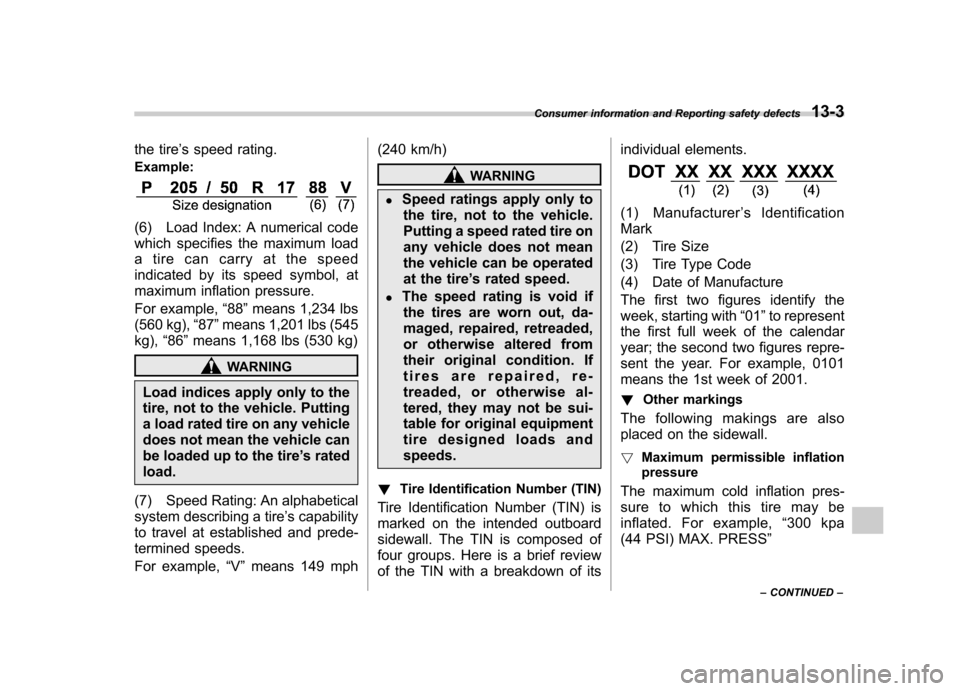
the tire’s speed rating.
Example:
(6) Load Index: A numerical code
which specifies the maximum load
a tire can carry at the speed
indicated by its speed symbol, at
maximum inflation pressure.
For example, “88 ”means 1,234 lbs
(560 kg), “87 ”means 1,201 lbs (545
kg), “86 ”means 1,168 lbs (530 kg)
WARNING
Load indices apply only to the
tire, not to the vehicle. Putting
a load rated tire on any vehicle
does not mean the vehicle can
be loaded up to the tire ’s rated
load.
(7) Speed Rating: An alphabetical
system describing a tire ’s capability
to travel at established and prede-
termined speeds.
For example, “V ” means 149 mph (240 km/h)
WARNING
. Speed ratings apply only to
the tire, not to the vehicle.
Putting a speed rated tire on
any vehicle does not mean
the vehicle can be operated
at the tire ’s rated speed.
. The speed rating is void if
the tires are worn out, da-
maged, repaired, retreaded,
or otherwise altered from
their original condition. If
tires are repaired, re-
treaded, or otherwise al-
tered, they may not be sui-
table for original equipment
tire designed loads andspeeds.
! Tire Identification Number (TIN)
Tire Identification Number (TIN) is
marked on the intended outboard
sidewall. The TIN is composed of
four groups. Here is a brief review
of the TIN with a breakdown of its individual elements.
(1) Manufacturer
’s Identification
Mark
(2) Tire Size
(3) Tire Type Code
(4) Date of Manufacture
The first two figures identify the
week, starting with “01 ”to represent
the first full week of the calendar
year; the second two figures repre-
sent the year. For example, 0101
means the 1st week of 2001.
! Other markings
The following makings are also
placed on the sidewall. ! Maximum permissible inflation
pressure
The maximum cold inflation pres-
sure to which this tire may be
inflated. For example, “300 kpa
(44 PSI) MAX. PRESS ”
Consumer information and Reporting safety defects
13-3
– CONTINUED –
Page 424 of 447
13-4Consumer information and Reporting safety defects
!Maximum load rating
The load rating at the maximum
permissible weight load for this tire.
For example, “MAX. LOAD 730 kg
(1609 LBS) @ 300 kpa (44 PSI)
MAX. PRESS. ”
WARNING
Maximum load rating applies
only to the tire, not to the
vehicle. Putting a load rated
tire on any vehicle does not
mean the vehicle can be
loaded up to the tire ’s rated
load.
! Construction type
Applicable construction of this tire.
For example, “TUBELESS STEEL
BELTED RADIAL ”
! Construction
The generic name of each cord
material used in the plies (both
sidewall and tread area) of this tire.
For example, “PLIES: TREAD 2 STEEL + 2 POLYESTER + 1
NYLON SIDEWALL 2 POLYE- STER
”
! Uniform Tire Quality Grading (UTQG)
For details, refer to “Uniform tire
quality grading standards ”in this
chapter.
Page 433 of 447

cified government test surfaces of
asphalt and concrete. A tire marked
C may have poor traction perfor- mance.
WARNING
The traction grade assigned to
this tire is based on straight-
ahead braking traction tests,
and does not include accel-
eration, cornering, hydroplan-
ing, or peak traction charac-teristics.
& Temperature A, B, C
The temperature grades are A (the
highest), B, and C, representing thetire ’s resistance to the generation of
heat and its ability to dissipate heat
when tested under controlled con-
ditions on a specified indoor labora-
tory test wheel. Sustained high
temperature can cause the material
of the tire to degenerate and reduce
tire life, and excessive temperature
can lead to sudden tire failure. The grade C corresponds to a level of
performance which all passenger
car tires must meet under the
Federal Motor Vehicle Safety Stan-
dards No. 109. Grades B and A
represent higher levels of perfor-
mance on the laboratory test wheel
than the minimum required by law.
WARNING
The temperature grade for this
tire is established for a tire
that is properly inflated and
not overloaded. Excessive
speed, underinflation, or ex-
cessive loading, either sepa-
rately or in combination, can
cause heat buildup and possi-
ble tire failure. Reporting safety defects (USA)
If you believe that your vehicle has
a defect which could cause a
crash or could cause injury or
death, you should immediately in-
form the National Highway Traffic
Safety Administration (NHTSA) in
addition to notifying Subaru of
America, Inc.
If NHTSA receives similar com-
plaints, it may open an investiga-
tion, and if it finds that a safety
defect exists in a group of vehi-
cles, it may order a recall and
remedy campaign. However,
NHTSA cannot become involved
in individual problems between
you, your dealer, or Subaru of
America, Inc. To contact NHTSA,
you may call the Vehicle Safety
Hotline toll-free at 1-888-327-4236
(TTY: 1-800-424-9153); go to
http://www.safercar.gov; or write
to: Administrator, NHTSA, 400
Seventh Street, SW., Washington,
Consumer information and Reporting safety defects
13-13
– CONTINUED –
Page 436 of 447
14-2Index
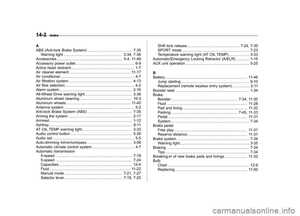
A
ABS (Anti-lock Brake System) ..................................... 7-35
Warning light ................................................. 3-34, 7-36
Accessories ....................................................... 5-4, 11-49
Accessory power outlet ................................................. 6-9
Active head restraint ..................................................... 1-7
Air cleaner element ................................................... 11-17
Air conditioner ............................................................. 4-7
Air filtration system ..................................................... 4-13
Air flow selection .......................................................... 4-2
Alarm system ............................................................ 2-16
All-Wheel Drive warning light ....................................... 3-36
Aluminum wheel cleaning ............................................ 10-3
Aluminum wheels ...................................................... 11-40
Antenna system ........................................................... 5-2
Anti-lock Brake System (ABS) ..................................... 7-35
Arming the system ..................................................... 2-17
Armrest ..................................................................... 1-12
Ashtray ..................................................................... 6-11
AT OIL TEMP warning light ......................................... 3-33
Audio control button ................................................... 5-26
Audio set .................................................................... 5-5
Auto-dimming mirror/compass ...................................... 3-56
Automatic climate control system ................................... 4-7
Automatic transmission 4-speed ................................................................ 7-18
5-speed ................................................................ 7-24
Capacities ............................................................. 12-4
Fluid .................................................................... 11-22
Manual mode ................................................ 7-21, 7-27
Selector lever ................................................ 7-19, 7-25 Shift lock release
............................................ 7-24, 7-30
SPORT mode ........................................................ 7-23
Temperature warning light (AT OIL TEMP) ................. 3-33
Automatic/Emergency Locking Retractor (A/ELR) ........... 1-15
AUX unit operation ..................................................... 5-25
BBattery .................................................................... 11-46
Jump starting ......................................................... 9-10
Replacement (remote keyless entry system) .............. 2-11
Booster seat .............................................................. 1-34
Brake Booster ....................................................... 7-34, 11-30
Fluid ................................................................... 11-28
Pad and lining ...................................................... 11-32
Parking ....................................................... 7-45, 11-33
Pedal .................................................................. 11-31
System .................................................................. 7-34
Brake pedal Free play ............................................................. 11-31
Reserve distance .................................................. 11-31
Brake system ............................................................. 7-34
Warning light .......................................................... 3-35
Braking ..................................................................... 7-34
Tips ...................................................................... 7-34
Breaking-in of new brake pads and linings ................... 11-32
Bulb Chart .................................................................... 12-9
Replacing ............................................................ 11-50