Page 414 of 652
13B-53
DIESEL INJECTION
Accelerometer: Removal - Refitting
K9K
13B
REMOVAL
I - REMOVAL PREPARATION OPERATION
aRemove the front engine cover.
aRemove:
-the dipstick,
-the oil level dipstick nut (1) ,
-the oil level dipstick guide.
aPlug the oil level dipstick guide inlet opening on the
cylinder block.
aDisconnect the following connectors :
-the heater plugs,
-the injectors,
-the flow actuator,-the diesel temperature sensor.
aDetach the channel at (2) .
aMove the wiring away from the channel.
aRemove:
-the nut (3) from the channel,
-the neck. Special tooling required
Emb. 1797Socket (24 mm) for removal -
refitting of the clutch master
cylinder
Equipment required
Diagnostic tool
Tightening torquesm
accelerometer20 N.m
114527
121419
Page 415 of 652

13B-54
DIESEL INJECTION
Accelerometer: Removal - Refitting
K9K
13B
II - OPERATION FOR REMOVAL OF PART
CONCERNED
aDisconnect the accelerometer connector (4) .
aRemove the accelerometer (4) using the (Emb.
1797).
REFITTING
I - REFITTING OPERATION FOR PART
CONCERNED
aRefit the accelerometer.
aTorque tighten the accelerometer (20 N.m) using
the (Emb. 1797).
aConnect the accelerometer connector.
II - FINAL OPERATION
aRefit:
-the channel,
-the channel nut.
aPosition the channel wiring harness.
aClip on the channel.
aConnect the connectors of:
-the heater plugs,
-the injectors,
-the flow actuator,
-the diesel temperature sensor.aRemove the blanking cover which protects the oil
level dipstick guide inlet opening on the cylinder
block.
aRefit:
-the dipstick guide,
-the oil level dipstick nut,
-the dipstick.
aRefit the channel nuts.
aRefit the engine cover.
109939
Note:
When replacing the accelerometer, run the
appropriate command (see Fault finding repair
manual) using the Diagnostic tool in order to
carr y out the necessary programming.
Page 417 of 652
13C-2
PREHEATING
Heater plugs: Removal - Refitting
K9K
13C
REMOVAL
I - REMOVAL PREPARATION OPERATION
aRemove the front engine cover.
aUnclip the fuel supply pipes (1) from the right-hand
suspended engine mounting.
aMove the fuel supply pipes away from the right-hand
suspended engine mounting.II - OPERATION FOR REMOVAL OF PART
CONCERNED
aDisconnect the heater plug connectors (2) .
aClean the edges of the heater plugs using a com-
pressed air nozzle to avoid any impurities getting
into the cylinders. Equipment required
compressed air nozzle
hinged wrench for heater plug
Tightening torquesm
heater plugs15 Nm
120045
127895
IMPORTANT
Wear goggles with side protectors for this opera-
tion.
Page 418 of 652
13C-3
PREHEATING
Heater plugs: Removal - Refitting
K9K
13C
a
aLoosen the heater plugs (3) using a 10 mm long ra-
dio socket connected to a universal joint or a hinged
wrench for heater plug.
aUse a hose to unscrew the heater plugscompletely.
aRemove the heater plugs.
aBlock the plug wells on the cylinder head using clean
cloths throughout the removal operation.
REFITTING
I - REFITTING OPERATION FOR PART
CONCERNED
aRemove the protection on the openings of the plug
well(s) on the cylinder head.
aBolt without tightening the heater plugs using the
hose.
aTorque tighten the heater plugs (15 Nm).
aConnect the heater plug connectors.
II - FINAL OPERATION.
aFit the fuel pipes on the right-hand suspended en-
gine mounting.aClip the fuel supply pipes onto the right-hand sus-
pended engine mounting.
aRefit the engine cover.
127905
Note:
If the heater plugs jam, use the heater plug
removal tool (see ) (Technical Note 5197A, 06A,
Tools).
Page 419 of 652

14A-1
ANTIPOLLUTION
Oil vapour rebreathing circuit: Descriptions
K9K
14A
I - PRESENTATION OF THE CIRCUIT
Operating phase A
Operating phase BOperating phase A :
-with the engine at low load, the vacuum in the air pipe
at the air filter box outlet is not sufficient to activate the
membrane of the oil vapour rebreathing valve, fitted
with a weighted spring. Oil vapours are aspirated in
large quantities due to the vacuum in the air pipe at
the air filter box outlet.
Operating phase B :
-At engine medium and high load, the vacuum in the
pipe at the air filter box outlet attracts the membrane
of the oil vapour rebreathing valve. The hole allowing
the oil vapours to pass through in large quantities is
therefore closed and the oil vapours are aspirated in
low quantities via a calibrated jet.
II - CHECK
To ensure the antipollution system works properly, the
oil vapour rebreathing circuit must be kept clean and in
good condition.
20965
20965-1
(P) Atmospher ic pressure
(1) Rocker cover
(2) Oil vapour recirculation pipe
(3) Oil vapour recirculation valve
(4) Air filter box outlet air pipe
(5) Turbocharger
Page 421 of 652
14A-3
ANTIPOLLUTION
Fuel vapour recirculation circuit: Check
D4F or D7F
14A
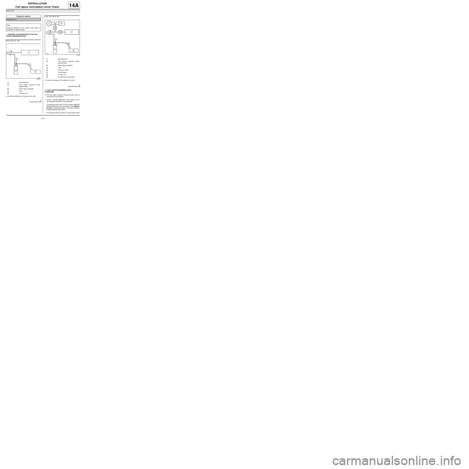
I - CHECKING THE OPERATION OF THE FUEL
VAPOUR ABSORBER BLEED
aCheck the condition of the pipes to the tank.aCheck the condition of the pipes to the tank.
II - FUEL VAPOUR ABSORBER BLEED
CONDITIONS
aThe fuel vapour absorber bleed solenoid valve is
controlled by the computer.
During « on board diagnostic » fault finding, fuel va-
pour absorber bleeding is not authorised.
The opening cyclic ratio of the fuel vapour absorber
bleed solenoid valve can be viewed on the Diagnos-
tic tool by reading parameter « Fuel vapour absorb-
er bleed solenoid valve OCR » .
The solenoid valve is closed for a value below 1.2%. Equipment required
Diagnostic tool
Note:
Incorrect operation of the system may result in
rough idle or engine stalling.
D4F, and 772 – D7F
97393-1
(1) Inlet distributor
(2) Fuel vapour absorber bleed
solenoid valve
(3) Petrol vapour absorber
(4) Tank
(5) Fresh air vent
D4F, and 780 or 782
121923
(1) Inlet distributor
(2) Fuel vapour absorber bleed
solenoid valve
(3) Petrol vapour absorber
(4) Tank
(6) Anti-retur n valve
(7) Turbocharger
(8) Air filter unit
(9) Air filter box air outlet pipe
Page 425 of 652

14A-7
ANTIPOLLUTION
Fuel vapour absorber: Check
D4F or D7F
14A
I - CHECKING THE FUEL VAPOUR ABSORBER
aOn the fuel vapour absorber, plug the circuit coming
from the fuel tank.
aConnect the pressure gauge of the (Mot. 1311-01)
to the fuel vapour absorber breather outlet.
aWith the engine at idle speed, check that no vacuum
is present at the fuel vapour absorber breather out-
let. In the same way, the control value read by the
Diagnostic tool in parameter « fuel vapour absorb-
er bleed solenoid valve OCR » remains minimal X
less than or equal to 1.5%.
Is there a vacuum?
-Yes: With the ignition off, use a manual vacuum
and pressure pump to apply a vacuum of 500
mbar to the solenoid valve outlet. The vacuum
pressure should not vary by more than 10 mbar
over 30 seconds.
•Does the pressure vary?
-Yes: the solenoid valve is faulty, replace it (see
17B, Petrol injection, Petrol injection: List
and location of components, page 17B-1) .
-No: if it is an electrical problem, check the circuit
(see MR 413 Fault finding, 17B, Petrol injec-
tion, Fault finding - Interpretation of faults,
Canister bleed solenoid valve circuit).
-No: In bleeding condition (see « bleeding
condition » ), the vacuum should increase. In the
same time, the value of the parameter on the Diag-
nostic tool increases.
II - CHECKING THE FUEL VAPOUR ABSORBER-
TANK CONNECTION
aCheck this connection by connecting a manual vac-
uum and pressure pump to the pipe leading to the
fuel vapour absorber.Special tooling required
Mot. 1311-01Pressure gauges and petrol
pressure measur ing unions.
Equipment required
Diagnostic tool
man ual vacuum and pressure pump
Page 428 of 652
14A-10
ANTIPOLLUTION
Exhaust gas recirculation solenoid valve: Removal - Refitting
K9K
14A
PARTS AND CONSUMABLES FOR THE
REPAIR WORK
aConsumables (see Vehicle: Parts and consuma-
bles for the repair) (02A, Parts and consumables):
-ABRASIVE PAD,
-SURFACE CLEANER.
REMOVAL
I - REMOVAL PREPARATION OPERATION
aRemove:
-the engine cover,
-the air filter box (see 12A, Fuel mixture, Air filter
unit: Removal - Refitting, page 12A-13) .
II - OPERATION FOR REMOVAL OF PART
CONCERNED
aRemove:
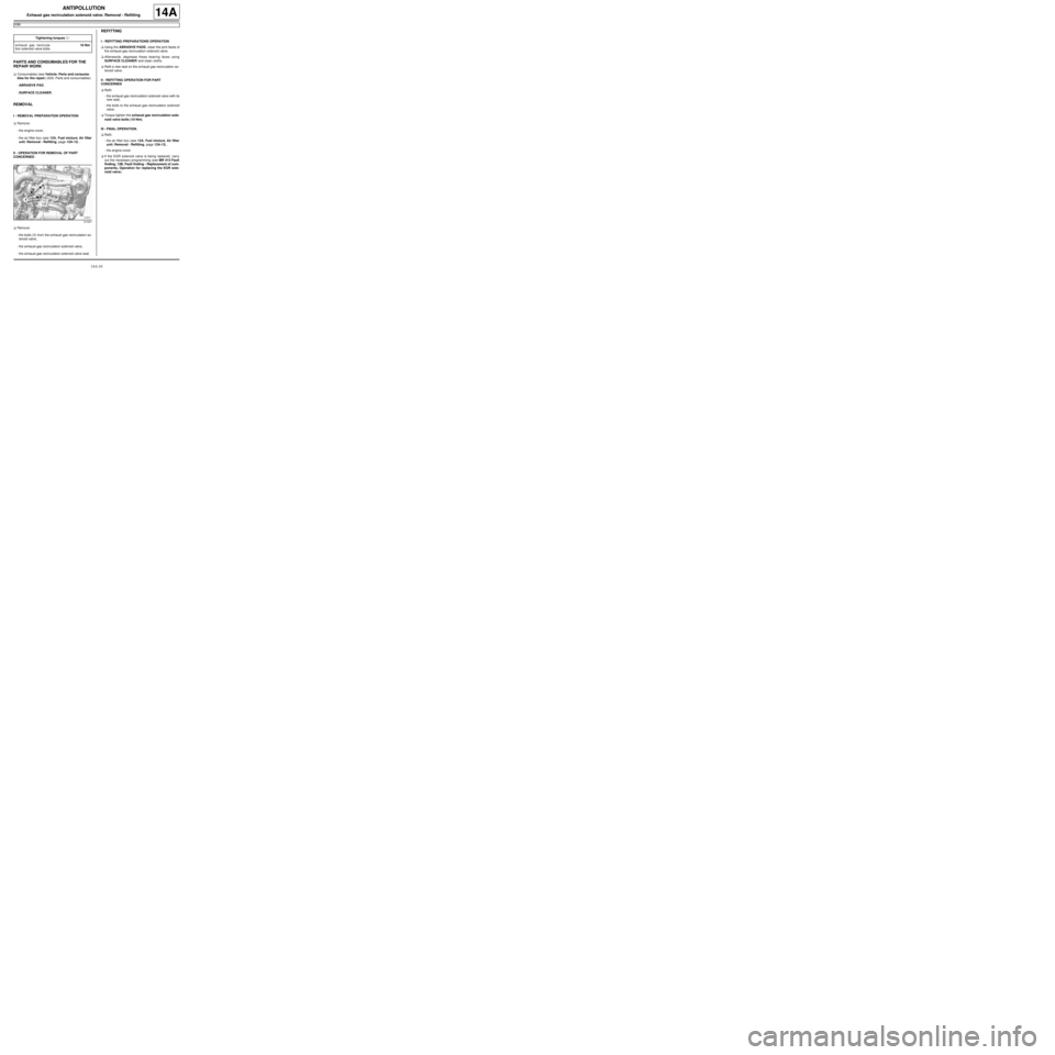
-the bolts (1) from the exhaust gas recirculation so-
lenoid valve,
-the exhaust gas recirculation solenoid valve,
-the exhaust gas recirculation solenoid valve seal.
REFITTING
I - REFITTING PREPARATIONS OPERATION
aUsing the ABRASIVE PADS, clean the joint faces of
the exhaust gas recirculation solenoid valve.
aAfterwards, degrease these bearing faces using
SURFACE CLEANER and clean cloths.
aRefit a new seal on the exhaust gas recirculation so-
lenoid valve.
II - REFITTING OPERATION FOR PART
CONCERNED
aRefit:
-the exhaust gas recirculation solenoid valve with its
new seal,
-the bolts to the exhaust gas recirculation solenoid
valve.
aTorque tighten the exhaust gas recirculation sole-
noid valve bolts (10 Nm).
III - FINAL OPERATION.
aRefit:
-the air filter box (see 12A, Fuel mixture, Air filter
unit: Removal - Refitting, page 12A-13) ,
-the engine cover.
aIf the EGR solenoid valve is being replaced, carry
out the necessary programming (see MR 413 Fault
finding, 13B, Fault finding - Replacement of com-
ponents, Operation for replacing the EGR sole-
noid valve). Tightening torquesm
exhaust gas recircula-
tion solenoid valve bolts10 Nm
121637