Page 306 of 652
12A-41
FUEL MIXTURE
Inlet distributor: Removal - Refitting
K4M
12A
aDisconnect:
-the throttle valve connector (4) ,
-the brake servo non-return valve at the inlet distrib-
utor.
aDisconnect the air inlet temperature sensor connec-
tor (5) .aDisconnect:
-all coil connectors (6) ,
-the inlet air pressure sensor connector (7) ,
-the camshaft dephaser solenoid valve connector
(8) .
aUnpick the wiring (9) .
aMove aside the wiring.
aDisconnect the petrol vapour recirculation pipe (10) .
132383
132369132370
131766
Page 307 of 652
12A-42
FUEL MIXTURE
Inlet distributor: Removal - Refitting
K4M
12A
II - REMOVAL OPERATION
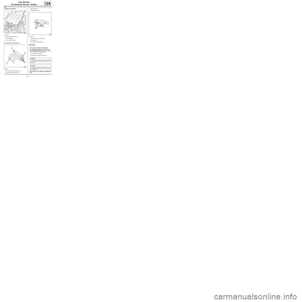
aRemove:
-the inlet distributor bolts (11) ,
-the inlet distributor,
-the inlet distributor seals.
When replacing the inlet distributor
aRemove:
-the air inlet temperature sensor (12) ,
-the air inlet pressure sensor (13) ,-the throttle valve,
-the throttle valve seal.
aRemove:
-the bolts (15) from the heat shield,
-the heat shield,
-the oil vapour rebreathing pipe.
REFITTING
I - REFITTING PREPARATION OPERATION
aUse SURFACE CLEANER (see Vehicle: Parts
and consumables for the repair) (04B, Consuma-
bles - Products) to clean and degrease:
-the inlet distributor joint face,
-the joint face of the injector holder shim.
aparts always to be replaced: inlet distributor
seal.
132371
132438
132439
WARNING
To ensure proper sealing, the gasket surfaces
must be clean, dry and not greasy (avoid any fin-
ger mar ks).
WARNING
Do not scrape the joint faces of the aluminium,
any damage caused to the joint face will result in
a risk of leaks.
Page 308 of 652
12A-43
FUEL MIXTURE
Inlet distributor: Removal - Refitting
K4M
12A
aFit new seals to the inlet distributor.
When replacing the inlet distributor
aparts always to be replaced: Throttle valve seal.
aUse SURFACE CLEANER (see Vehicle: Parts
and consumables for the repair) (04B, Consuma-
bles - Products) to clean and degrease:
-the throttle valve joint face if it is to be re-used,
-the inlet distributor seal housing.
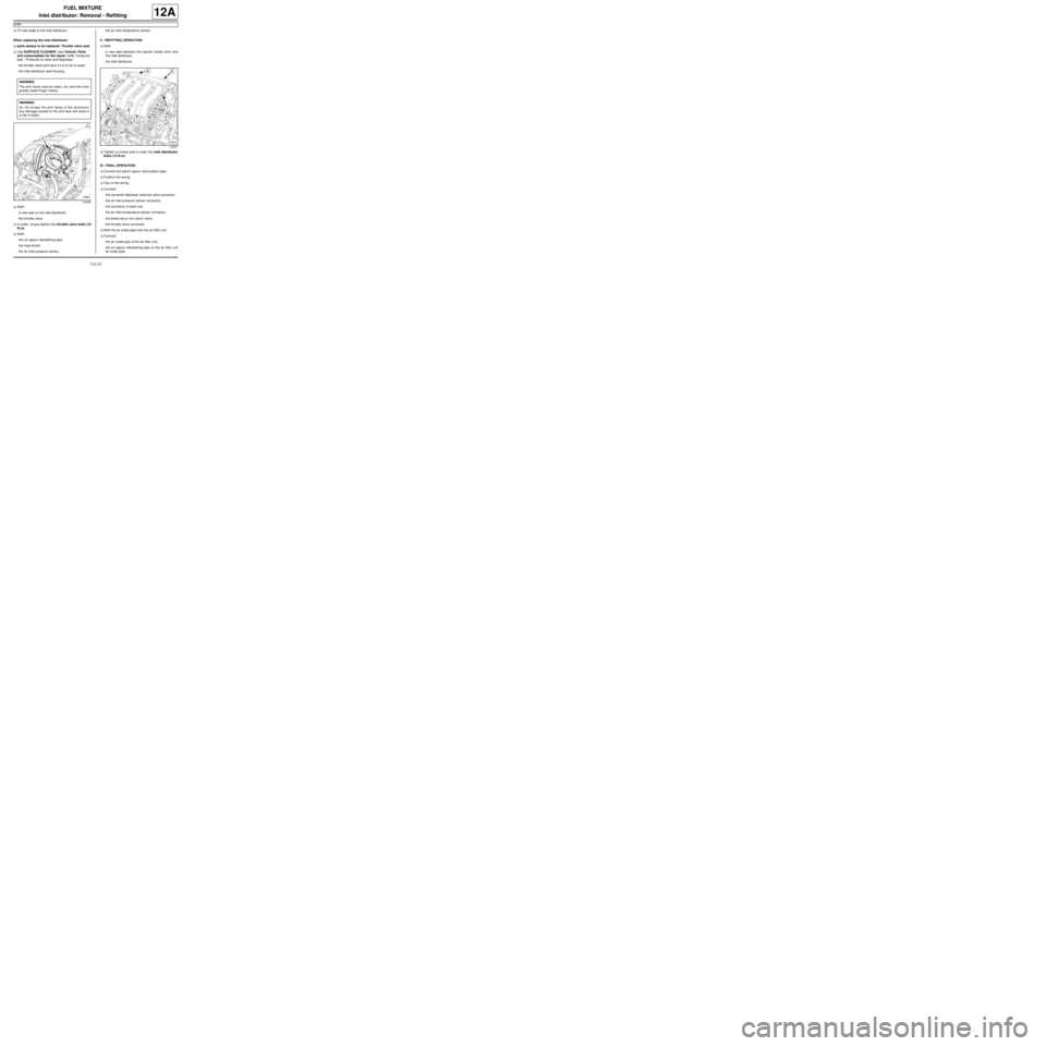
aRefit:
-a new seal on the inlet distributor,
-the throttle valve.
aIn order, torque tighten the throttle valve bolts (10
N.m).
aRefit:
-the oil vapour rebreathing pipe,
-the heat shield,
-the air inlet pressure sensor,-the air inlet temperature sensor.
II - REFITTING OPERATION
aRefit:
-a new seal between the injector holder shim and
the inlet distributor,
-the inlet distributor.
aTighten to torque and in order the inlet distributor
bolts (12 N.m).
III - FINAL OPERATION
aConnect the petrol vapour recirculation pipe.
aPosition the wiring.
aClip on the wiring.
aConnect:
-the camshaft dephaser solenoid valve connector,
-the air inlet pressure sensor connector,
-the connector of each coil,
-the air inlet temperature sensor connector,
-the brake servo non-return valve,
-the throttle valve connector.
aRefit the air outlet pipe onto the air filter unit.
aConnect:
-the air outlet pipe of the air filter unit,
-the oil vapour rebreathing pipe on the air filter unit
air outlet pipe. WARNING
The joint faces must be clean, dr y and free from
grease (avoid finger marks).
WARNING
Do not scrape the joint faces of the aluminium,
any damage caused to the joint face will result in
a risk of leaks.
132383
132371
Page 341 of 652
12B-16
TURBOCHARGING
Turbocharger oil pipe: Removal - Refitting
C44, and K9K
12B
REMOVAL
I - REMOVAL PREPARATION OPERATION
aPosition the vehicle on a two-post lift (see Vehicle:
Towing and lifting) (02A, Lifting equipment).
aRemove the front engine cover.
aDisconnect the battery (see Battery: Removal - Re-
fitting) (80A, Battery).
1 - Turbocharger oil supply pipe
aRemove:
-the windscreen wiper arms (see Windscreen wip-
er arm: Removal - Refitting) (85A, Wiping -
Washing),
-the scuttle panel grille (see Scuttle panel grille:
Removal - Refitting) (56A, Exterior equipment),
-the scoop under the scuttle panel grille (see Scoop
under the scuttle panel grille: Removal - Refit-
ting) (56A, Exterior equipment),
-the air filter box (see 12A, Fuel mixture, Air filter
unit: Removal - Refitting, page 12A-13) ,
-the exhaust gas recirculation solenoid valve (see
14A, Antipollution, Exhaust gas recirculation
solenoid valve: Removal - Refitting, page 14A-
10) .
2 - turbocharger oil return pipe
aRemove the catalytic converter (see 19B, Exhaust,
Catalytic converter: Removal - Refitting, page
19B-12) .II - OPERATION FOR REMOVAL OF PART
CONCERNED
1 - Turbocharger oil supply pipe
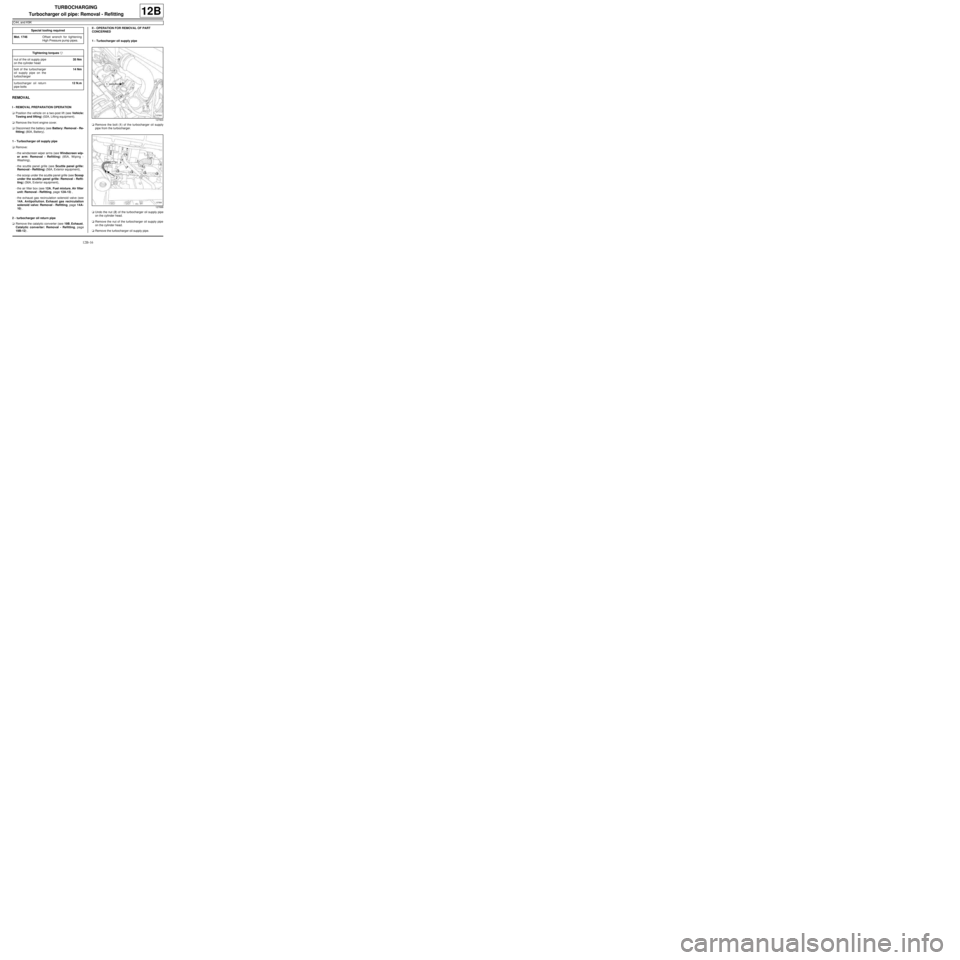
aRemove the bolt (1) of the turbocharger oil supply
pipe from the turbocharger.
aUndo the nut (2) of the turbocharger oil supply pipe
on the cylinder head.
aRemove the nut of the turbocharger oil supply pipe
on the cylinder head.
aRemove the turbocharger oil supply pipe. Special tooling required
Mot. 1746Offset wrench for tightening
High Pressure pump pipes.
Tightening torquesm
nut of the oil supply pipe
on the cylinder head35 Nm
bolt of the turbocharger
oil supply pipe on the
turbocharger14 Nm
turbocharger oil return
pipe bolts12 N.m
127900
127898
Page 344 of 652
13A-1
FUEL SUPPLY
Diesel supply circuit: Operating diagram
K9K
13A
The diesel fuel supply system includes a diesel injec-
tion computer and various sensors.
120417
(1) Fuel tank
(2) Dipstick
(3) Electrical diesel fuel reheater
(4) Man ual priming pump
(5) Diesel filter
(6) High pressure pump
(7) Fuel fl ow actuator
(8) Injector rail
(9) Injector rail pressure sensor
(10) Diesel injector
(11) Venturi
IMPORTANT
Loosening a high pressure pipe union when the
engine is running is strictly prohibited.
WARNING
It is forbidden:
-to dismantle the interior of the pump or injectors.
-to remove the pressure sensor from the fuel rail
(because of circuit contamination problems). If the
pressure sensor fails, the pressure sensor, the rail
and the five high pressure pipes must be replaced,
-to dismantle the flow regulator solenoid valve and
the pressure regulator solenoid valve on the high
pressure pump.
Page 347 of 652
13A-4
FUEL SUPPLY
Fuel filter: Removal - Refitting
K9K
13A
PARTS AND CONSUMABLES FOR THE
REPAIR WORK
aCONSUMABLES:
-cleaning cloths.
aMake sure you have a new diesel filter before open-
ing the fuel circuit.
REMOVAL
I - REMOVAL PREPARATION OPERATION
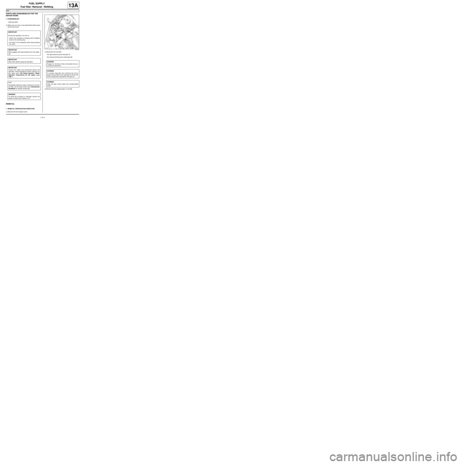
aRemove the front engine cover.aDisconnect the fuel filter:
-the high pressure pump inlet pipe (1) ,
-the manual priming pump outlet pipe (2) .
aRemove the fuel supply pipes (1) and (2) . IMPORTANT
During this operation, be sure to:
-refrain from smoking or bringing red hot objects
close to the working area,
-be careful of fuel splashes when disconnecting
the union.
IMPORTANT
Wear goggles with side protectors for this opera-
tion.
IMPORTANT
Wear latex gloves during the operation.
IMPORTANT
Consult the safety and cleanliness advice and
operation recommendations before carrying out
any repair (see 13B, Diesel injection, Diesel
injection: Precautions for the repair, page
13B-1) .
Note:
Periodically bleed the water contained in the die-
sel filter via the bleed screw (see maintenance
handbook for vehicle concerned).
WARNING
To avoid any corrosion or damage, protect the
areas on which fuel is likely to run.
121441
WARNING
Prepare for the flow of fluid, and protect the sur-
rounding components.
WARNING
To prevent impur ities from entering the circuit,
plugs must be fitted to the openings of all the fuel
circuit components exposed to the open air.
WARNING
Keep the pipe unions away from contaminated
areas.
Page 348 of 652
13A-5
FUEL SUPPLY
Fuel filter: Removal - Refitting
K9K
13A
II - OPERATION FOR REMOVAL OF PART
CONCERNED
aRemove:
-the fuel filter mounting nut (3) ,
-the fuel filter from its mounting.
aDetach the water detection sensor offset connector
on the fuel filter mounting (if fitted).
REFITTING
I - REFITTING OPERATION FOR PART
CONCERNED
aaAttach the water detection sensor offset connector
to the fuel filter mounting (if fitted).
aRefit the fuel filter to its mounting.
aFit the fuel filter mounting nut.
II - FINAL OPERATION.
aPosition the fuel pipes.
aConnect to the fuel filter:
-the manual priming pump outlet pipe,
-the high pressure pump inlet pipe.
aOpen the bleed screw on top of the fuel filter.
aPrime the fuel circuit using a manual priming pump
until the disconnected pipes are filled with fuel.
aClose the bleed screw on top of the fuel filter.
aCheck that there are no fuel leaks.
aStart the engine.
aCheck that there are no fuel leaks.
aSwitch off the engine.
aRefit the engine cover.
BLEEDING
aRemove the fuel filter mounting nut.
aDetach the manual priming pump.
aRemove the fuel filter without pulling on the water
detection sensor wiring harness in the diesel fuel.
aPosition a container under the fuel filter which has
been removed from its mounting.
aTurn the bleed cap or the water detection sensor in
the diesel fuel (depending on equipment) by no
more than one turn.
aAllow it to flow until diesel fuel appears.
aClose the bleed cap or the water detection sensor
(depending on equipment).
121441
Note:
If the fuel filter is to be reused, fit blanking plugs
to the fuel supply pipes and fuel filter openings,
using the appropriate blanking plug kit, depend-
ing on the engine (see 13B, Diesel injection,
Diesel injection: Precautions for the repair,
page 13B-1) .
WARNING
Do not remove the blanking plugs from each
component until the last moment.
Also, do not remove the components from their
packaging until they are to be fitted to the vehi-
cle.
Note:
Chec k that the fuel filter is correctly positioned
and secure on its mounting by shaking it: the fil-
ter must not move.
WARNING
Prepare for the flow of fluid, and protect the sur-
rounding components.
Page 351 of 652
13A-8
FUEL SUPPLY
Fuel circuit: Operating diagram
D4F or D7F or K4M
13A
Operating diagram of the fuel supply circuit ( « pump - sender - fuel filter » assembly)
The fuel supply circuit does not have a return.
The fuel pressure does not vary with engine load.
The circuit comprises:
-a rail (1) without a return pipe union and without a
supply pressure regulator,
-a single pipe (2) coming from the tank,
-a « pump - sender - fuel filter » supply assembly fitted
with a pressure regulator (3) , fuel pump (4) and fuel
filter (5) (all located in the tank),
-a fuel vapour recirculation tank (6) .
109471