2009 RENAULT TWINGO RS sensor
[x] Cancel search: sensorPage 66 of 652

10A-60
ENGINE AND CYLINDER BLOCK ASSEMBLY
Oil pressure: Check
D4F or D7F or K9K
10A
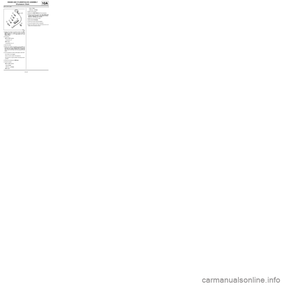
aPosition the engine oil pressure sensor tool (Mot.
836-05) fitted with suitable end pieces using the
(Mot. 1495-01) or a 1/2" long socket (12.7 mm
square drive).
aEnd pieces:
-D4F and D7F engines:
•end piece C + F
-K9K engine:
•end piece E + C + F
aStart the vehicle.
aMonitor the engine oil pressure as the engine oil
temperature increases (approximately 80˚C or the
first time the engine cooling fan is triggered)
which must not be lower than the pressure at idle
speed.
aIf the oil pressure is lower at idle speed, check that:
-the oil filter is not clogged,
-there is no dirt or swarf in the engine oil,
-the oil pump is in good condition and being correct-
ly driven.
aCheck the oil pressure at 3000 rpm.
aCheck the values:
-D4F and D7F engines:
•Idling: 0.8 bar
•3000 rpm: < 3.5 bars
-K9K engine•idling: 1.2 bar
•3000 rpm: < 3.5 bars
aSwitch off the engine.
aRemove the (Mot. 836-05) with the end pieces.
aRefit the oil pressure sensor (see 10A, Engine and
cylinder block assembly, Oil pressure sensor:
Removal - Refitting, page 10A-45) .
aWipe any oil run-off with a cloth.
aWait at least 10 minutes.
aCheck the oil level using the dipstick.
aTop up the engine oil level if necessary.
aStart the vehicle and check that there are no oil
leaks at the oil pressure sensor.
87363
Page 67 of 652

10A-61
ENGINE AND CYLINDER BLOCK ASSEMBLY
Oil pressure: Check
K4M
10A
Oil pressure tables:
End pieces to be used:
I - REMOVAL PREPARATION OPERATION
a
II - CHECK
aRemove the oil pressure sensor (see 10A, Engine
and cylinder block assembly, Oil pressure sen-
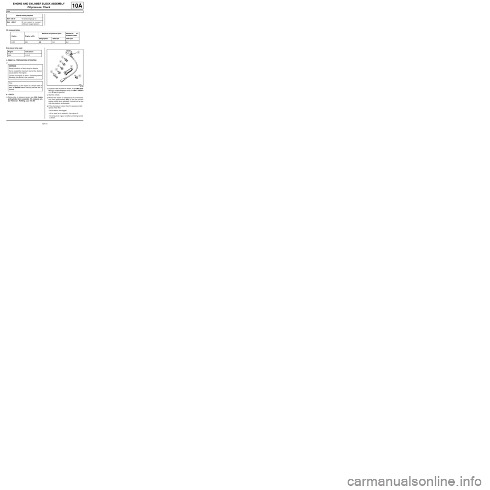
sor: Removal - Refitting, page 10A-45) .aIn place of the oil pressure sensor, fit the (Mot. 836-
05) with suitable adapters using the (Mot. 1495-01)
or a 22 mm long socket.
aStart the vehicle.
aMonitor the engine oil pressure as the oil tempera-
ture rises (approximately 80˚C or the first time the
engine cooling fan is activated); it should not be less
than the pressure at idle speed.
aIf the oil pressure is lower than the pressure at idle
speed, check that:
-the oil filter is not clogged,
-dirt or swarf is not present in the engine oil,
-the oil pump is in good condition and being correct-
ly driven. Special tooling required
Mot. 836-05Oil pressure gauge kit.
Mot. 1495-0122 mm socket for removal -
refitting of oxygen sensors.
Engine Engine suffixMinimum oil pressure (bar) Maximu m o i l
pressure (max)
Idling speed 4000 rpm 4000 rpm
K4M 8540.5 3.1 4.4
Engine End pieces
K4M E+C+F
WARNING
Always check the oil level using the dipstick.
Do not exceed the maximum level on the dipstick
(could destroy the engine).
Correct the engine oil level if necessary before
delivering the vehicle to the customer.
Note:
When topping up the engine oil, always leave at
least 10 minutes before checking the level with a
dipstick.
87363
Page 68 of 652

10A-62
ENGINE AND CYLINDER BLOCK ASSEMBLY
Oil pressure: Check
K4M
10A
aCheck the oil pressure in comparison with the values
given in the table above.
aSwitch off the engine.
aRemove the (Mot. 836-05) with the end pieces.
aRefit the oil pressure sensor (see 10A, Engine and
cylinder block assembly, Oil pressure sensor:
Removal - Refitting, page 10A-45) .
aWipe any oil run-off with a cloth.
aWait at least 10 minutes.
aCheck the oil level using the dipstick.
aTop up the oil level if necessary (see Engine oil:
Specifications) (Technical Note 6013A, 04A, Lubri-
cants).
aStart the vehicle and check that there are no oil
leaks at the oil pressure sensor.
Page 84 of 652

10A-78
ENGINE AND CYLINDER BLOCK ASSEMBLY
Engine - gearbox assembly: Removal - Refitting
D4F or D7F
10A
aDrain the coolant circuit (see Refrigerant circuit:
Draining - Filling) .
aRemove:
-the air conditioning pipe bolts on the compressor,
-the air conditioning pipe bolt on the dehydrator res-
ervoir.
aDisconnect the air conditioning pressostat connec-
tor.
a
aDisconnect the fuel supply pipe union.
aInsert the blanking plugs.
aUnclip the fuel pipe on the upper timing cover.aSet the wheels straight ahead.
aPosition the flywheel immobiliser.
aRemove the cover from the universal joint (do not
keep).
aRemove the universal joint bolt (do not keep).
aRemove the universal joint from the steering box.
aDetach the electrical wiring on the cross member.
aLoosen the tie rod lower bolts.
aRemove:
-the tie rod upper bolts.
-the track rod end nuts,
-the track rod ends using the (Tav. 476),
-the lower guide pin bolts,
-the brake pads,
-the calliper mounting bolts,
-the brake callipers, and attach them to the suspen-
sion springs,
-the ABS sensor bolts (if fitted to the vehicle),
-the ABS sensors,
-the shock absorber base lower bolts, AIR CONDITIONING
WARNING
To prevent moisture from entering the system,
place plugs on the cold loop components which
are open to the air.
IMPORTANT
During this operation, be sure to:
-refrain from smoking or bringing red hot objects
close to the working area,
-be careful of fuel splashes when disconnecting
the union.
IMPORTANT
Wear leaktight gloves (Nitrile type) for this opera-
tion.
WARNING
To avoid any corrosion or damage, protect the
areas on which fuel is likely to run.
119544
Page 89 of 652

10A-83
ENGINE AND CYLINDER BLOCK ASSEMBLY
Engine - gearbox assembly: Removal - Refitting
D4F or D7F
10A
aTorque tighten:
-the front subframe bolts (62 N.m),
-the rear subframe bolts (105 N.m),
-the subframe rear tie rod inner bolts (21 N.m),
-the subframe rear tie rod outer bolts (90 N.m),
-the engine tie-bar bolts on the gearbox (105
N.m),
-the engine tie-bar bolt on the subframe (105
N.m).
aRefit the control cables onto the gearbox.
aRemove the blanking plugs from the openings.
aClip the clutch pipe onto the gearbox.
aConnect the clutch slave cylinder.
aRemove the hose clamp (Ms. 583).
aBleed the clutch circuit (see Clutch circuit: Bleed) .
aRefit the gear control linkage.
aAttach the gear control linkage to:
-the gear lever,
-the control lever on the gearbox.
aRefit:
-the heat shield,
-the heat shield bolts.
aRefit the clutch control cable on the manual gearbox.
aRefit the catalytic converter (see 19B, Exhaust,
Catalytic converter: Removal - Refitting, page
19B-12) .aRefit the exhaust downpipe.
aFit the clip.
aTighten the intermediate pipe clip.
aRefit the exhaust downpipe bolts.
aTorque tighten the exhaust downpipe bolts (9
N.m).
aRefit:
-the shock absorber base lower bolts,
-the ABS sensors,
-the ABS sensor bolts (if fitted to the vehicle),
-the brake callipers,
-the calliper mounting bolts,
-the brake pads,
-the lower guide pin bolts,
-track rod ends,
-the track rod end nuts,
-the tie rod upper bolts.
aTorque tighten:
-the shock absorber base lower bolts (105 N.m ),
-the calliper mounting bolts (105 N.m),
-the lower guide pin bolts (34 N.m),
-the track rod end nuts (37 N.m),
-the tie rod upper bolts (21 N.m),
-the tie rod lower bolts (62 N.m).
aClip the electrical wiring on to the cross member.
aFit the steering box universal joint.
aRefit the universal joint bolt.
aTorque tighten the universal joint (24 N.m).
aRemove the flywheel immobiliser.
aClip the fuel pipe on to the upper timing cover.
aConnect the fuel supply pipe union.
aConnect the air conditioning pressostat connector. JH3
JB1 or JH1
D4F, and 772 – D7F
D4F, and 780 or 782
AIR CONDITIONING
Page 107 of 652

10A-101
ENGINE AND CYLINDER BLOCK ASSEMBLY
Engine - gearbox assembly: Removal - Refitting
K4M
10A
aRemove:
-the bolt (27) from the « compressor - intermediate
pipe » connecting pipe,
-the bolt (28) on the « compressor - condenser »
connecting pipe,
-the bolt (29) from the « compressor - intermediate
pipe » connecting pipe mounting.
aDisconnect:
-the pressure sensor connector (30) ,
-the « compressor - intermediate pipe » connecting
pipe,-the « compressor - condenser » connecting pipe.
aInsert the blanking plugs.
aDisconnect the brake servo vacuum pipe union (31)
.
131782
132335
WARNING
To prevent moisture from entering the system,
place plugs on the cold loop components which
are open to the air.
121348
Page 109 of 652

10A-103
ENGINE AND CYLINDER BLOCK ASSEMBLY
Engine - gearbox assembly: Removal - Refitting
K4M
10A
-the rubber pad mounting from the suspended en-
gine mounting on the gearbox.
aRemove the right-hand suspended engine mounting
(see 19D, Engine mounting, Right-hand sus-
pended engine mounting: Removal - Refitting,
page 19D-13) .
aLift the vehicle to remove the "engine and gearbox"
assembly.
REFITTING
I - REFITTING PREPARATION OPERATION
aFor standard engine replacement (see Standard re-
placement) (Technical Note 6023A, 10A, Engine
and peripherals).
II - REFITTING OPERATION
aPosition the "engine and gearbox" assembly in the
body.
aRefit the right-hand suspended engine mounting
(see 19D, Engine mounting, Right-hand sus-
pended engine mounting: Removal - Refitting,
page 19D-13) .
aRefit the rubber pad mounting from the suspended
engine mounting on the gearbox.
aTorque tighten the rubber pad mounting bolts for
the suspended engine mounting on the gearbox
(21 N.m).
aRefit the suspended engine mounting rubber pad.
aTorque tighten:
-the bolts of the suspended mounting rubber
pad (62 N.m),
-the suspended engine mounting shaft nut (62
N.m).
III - FINAL OPERATION
aRemove the.
aRemove the blanking plugs.
aConnect:
-the union of the brake servo vacuum pipe,
-the « compressor - condenser » connecting pipe,-the « compressor - intermediate pipe » connecting
pipe,
-the pressure sensor connector,
aConnect the hose on the coolant pump inlet pipe.
aFit the hose clip on the coolant pump inlet pipe using
the (Mot. 1448).
aRefit the earth nuts.
aClip:
-the relay plates on the engine compartment con-
nection unit,
-the fuse holders.
aConnect the fuses.
aRefit the engine compartment connection unit on the
body.
aConnect the connector to the engine compartment
connection unit.
aRefit the engine compartment connection unit cover.
aClip:
-the wiring on the engine cooling fan assembly,
-the cooling radiator top and bottom hoses on the
engine cooling fan assembly.
aConnect:
-the engine cooling fan assembly resistor connec-
tor,
-the engine cooling fan assembly connector.
aRemove the blanking plug from the fuel supply pipe
opening and the injector rail fuel opening.
aReconnect the fuel supply pipe.
aClip the fuel supply pipe in place.
aConnect:
-the fuel vapour absorber bleed solenoid valve con-
nector,
-the fuel vapour absorber bleed solenoid valve pipe.
aFit the gearbox control cables.
aClip the manual gearbox control cables onto:
-the gear selectors,
-the cable sleeve stops.
aRemove the blanking plug from the hydraulic clutch
control pipe opening and the opening of the clutch
thrust bearing.
aConnect the hydraulic clutch control pipe.
aClip the hydraulic clutch control pipe on the gearbox. Note:
Check no component obstructs the movement of
the body around the engine - gearbox assembly.
Page 140 of 652

11A-23
TOP AND FRONT OF ENGINE
Crankshaft accessories pulley: Removal - Refitting
C44, and K9K
11A
PARTS AND CONSUMABLES FOR THE
REPAIR WORK
aParts always to be replaced:
-accessories belt,
-accessories belt auto tensioner,
-accessories belt auto tensioner bolt.
REMOVAL
I - REMOVAL PREPARATION OPERATION
aPosition the vehicle on a two-post lift ( (see Vehicle:
Towing and lifting) ).aDisconnect the battery ( (see Battery: Removal -
Refitting) ).
aRemove:
-the front right-hand wheel ( (see Wheel: Removal
- Refitting) ),
-the front right-hand wheel arch liner ( (see Front
wheel arch liner: Removal - Refitting) ),
-the accessories belt (see 11A, Top and front of
engine, Accessories belt: Removal - Refitting,
page 11A-3) ,
-the accessories belt auto tensioner.
II - OPERATION FOR REMOVAL OF PART
CONCERNED
aRemove:
-the crankshaft position sensor (see 13B, Diesel in-
jection, Crankshaft position sensor: Removal -Refitting, page 13B-15) , Tightening torquesm
crankshaft accessories
pulley bolt80 Nm
19656