Page 250 of 652

11A-133
TOP AND FRONT OF ENGINE
Cylinder head: Removal - Refitting
D4F, and 780 or 782
11A
2 - Checking the gasket face
aCheck the flatness of the cylinder head gasket face
(see Cylinder head: Check) .
3 - Optional additional operations
aWhen replacing the cylinder head, strip the cylinder
head (see Cylinder head: Stripping - Rebuilding) .
aIf necessary, carry out a complete check of the cylin-
der head (see Cylinder head: Check) .
II - REFITTING OPERATION FOR PART
CONCERNED
aBring the pistons to mid-stroke position to prevent
them from coming into contact with the valves during
the tightening of the cylinder head.
aCheck for the cylinder head centring dowels on the
cylinder block.
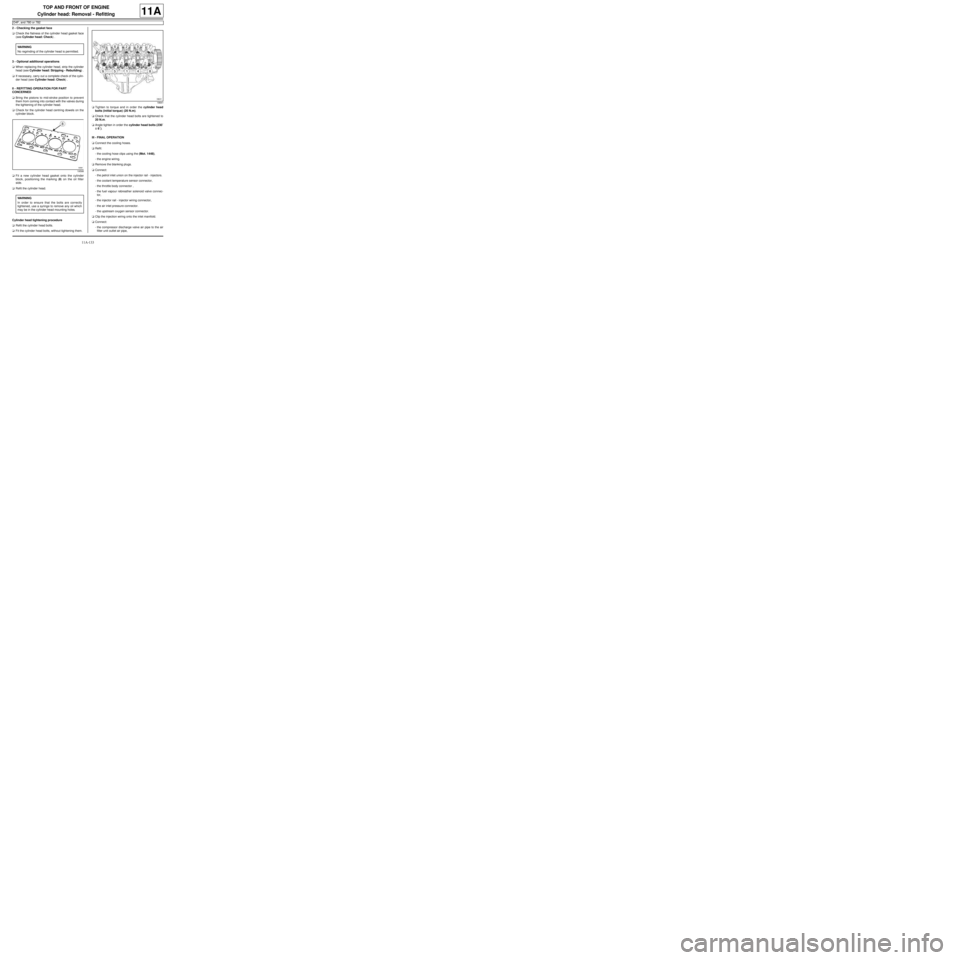
aFit a new cylinder head gasket onto the cylinder
block, positioning the marking (8) on the oil filter
side.
aRefit the cylinder head.
Cylinder head tightening procedure
aRefit the cylinder head bolts.
aFit the cylinder head bolts, without tightening them.aTighten to torque and in order the cylinder head
bolts (initial torque) (20 N.m).
aCheck that the cylinder head bolts are tightened to
20 N.m.
aAngle tighten in order the cylinder head bolts (230˚
±± ± ±
6˚).
III - FINAL OPERATION
aConnect the cooling hoses.
aRefit:
-the cooling hose clips using the (Mot. 1448),
-the engine wiring.
aRemove the blanking plugs.
aConnect:
-the petrol inlet union on the injector rail - injectors.
-the coolant temperature sensor connector,
-the throttle body connector ,
-the fuel vapour rebreather solenoid valve connec-
tor,
-the injector rail - injector wiring connector,
-the air inlet pressure connector.
-the upstream oxygen sensor connector.
aClip the injection wiring onto the inlet manifold.
aConnect:
-the compressor discharge valve air pipe to the air
filter unit outlet air pipe, WARNING
No regrinding of the cylinder head is permitted.
19598
WARNING
In order to ensure that the bolts are correctly
tightened, use a syringe to remove any oil which
may be in the cylinder head mounting holes.
18641
Page 370 of 652
13B-9
DIESEL INJECTION
Diesel injection: List and location of components
K9K, and 740
13B
121436
(11) Pre-postheating unit
120039
(12) Turbocharging pressure sensor
(13) Exhaust gas recirculation sole-
noid valve
(14) Coolant temper ature sensor
(15) Turbocharger upstream inlet air
temperature sensor
(16) Turbocharger downstream inlet
air temperature sensor
120326
(17) Cylinder position sensor
120327
(18) Engine speed and position sen-
sor
Page 372 of 652
13B-11
DIESEL INJECTION
Diesel injection: List and location of components
K9K, and 718
13B
141220
(11) Pre-postheating unit
120039
(12) Turbocharger pressure sensor
(13) Exhaust gas recirculation sole-
noid valve
(14) Coolant temper ature sensor
(15) Air inlet temperature sensor
upstream of the turbocharger
(16) Air inlet temperature sensor
downstream of the turbocharger
120326
(17) Cylinder reference sensor
120327
(18) Crankshaft position sensor
Page 395 of 652

13B-34
DIESEL INJECTION
High pressure pipe: Check
K9K
13B
a
CHECK
aRemove the front engine cover.
aPrime the fuel circuit with the manual priming pump
until the disconnected pipes are filled with fuel (auto-
matic degassing).
aCheck that there are no fuel leaks.
aConnect the Diagnostic tool to the vehicle.aDeal with present faults,
aActivate command AC029 “high pressure circuit
sealing test”.
aCheck that there are no fuel leaks.
aDeal with the causes of any possible leaks.
aUse the Diagnostic tool to check for stored faults;
deal with these and clear them as necessary.
aDisconnect the Diagnostic tool.
aRefit the engine cover. Equipment required
Diagnostic tool
Note:
Check that there are no diesel leaks after each
operation.
Note:
The Diagnostic tool can be used to test the high
pressure circuit with the engine running. This
command can be used to run fault finding on a
leak due to an incorrectly fitted or tightened
union. This command only works if the engine
coolant temperature is greater than 60˚. The fault
finding procedure will not reveal small leaks due
to incorrect tightening.
IMPORTANT
Consult the safety and cleanliness advice and
operation recommendations before carrying out
any repair (see 13B, Diesel injection, Diesel
injection: Precautions for the repair, page
13B-1) .Note:
Certain faults will prevent this test from being
carr ied out: deal with them first.
Note:
The engine automatically runs a cycle of four
acceler ations and decelerations to lower the rail
pressure.
Note:
Do not leave anything on the engine compart-
ment dur ing the test phase (significant vibration).
Page 476 of 652
17B-1
PETROL INJECTION
Petrol injection: List and location of components
D4F, and 772
17B
121740
(1) Petrol vapour rebreathing sole-
noid valve
(2) Intake air pressure sensor
(3) Motorised throttle valve
(4) Injection computer
121739
(5) Intake air temperature sensor
(6) Pinking sensor
(7) Coolant temper ature sensor
(8) Engine speed and flywheel posi-
tion sensor
113044
(9) Ignition coil
Page 484 of 652
17B-9
PETROL INJECTION
Petrol injection: List and location of components
K4M
17B
131776
(1) Fuel vapour absorber bleed
solenoid valve
(2) Camshaft dephaser solenoid
valve
(3) Air inlet pressure sensor
(4) Coil
(5) Throttle valve
(6) Petrol injection computer
(7) Switching protection unit
(8) Coolant temper ature sensor
(9) Camshaft position sensor
(10) Pinking sensor
(11) Oil pressure sensor
(12) Air temperature sensor
(13) Injector rail
131766
(1) Fuel vapour absorber bleed
solenoid valve
Page 511 of 652
19A-1
COOLING
Engine cooling system: Specifications
D4F or D7F or K4M or K9K
19A
Vehicles in the current range have cooling systems
with the following basic specifications:
-hermetically-sealed pressurised circuit (with expan-
sion bottle valve),
-circuit using only type « D » fluid,
-passenger compartment heating system equipped
with a « heater matrix » type radiator located under
the dashboard which helps to cool the engine.
Coolant quantities
Special notes:
-protection down to - 25˚C ±± ± ±
2 for cold and temperate
countries,
-protection down to - 40˚C ±± ± ±
2 for "extreme cold" coun-
tries.
Thermostat opening temperaturesEngine Quantity
(litres)Grade
D7F 800 5.5
Only use coolant
GLACEOL RX
(type D) D4F 772 5.5
K9K 740 5.7
D4F 780 5.7
D4F 782 5.7
K4M 854 5.7
Engine Star t o f
opening (˚C)Fully open (˚C)
D7F89 99
D4F89 99 ±± ± ±
2
K9K83 ±± ± ±
395
K4M89 101
Page 554 of 652

19A-44
COOLING
Water chamber: Removal - Refitting
K9K
19A
aDrain the cooling system (see 19A, Cooling, Cool-
ing system: Draining - Refilling, page 19A-9) .
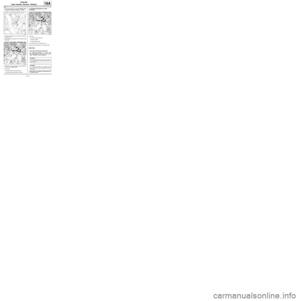
aUnclip the cooling hose of the coolant-oil heat ex-
changer at (11) .
aMove aside the cooling hose of the coolant-oil heat
exchanger.
aSeparate the clips of the water chamber cooling hos-
es (12) using the (Mot. 1448).
aDisconnect:
-the water chamber cooling hoses (12) ,
-the coolant temperature sensor connector.II - OPERATION FOR REMOVAL OF PART
CONCERNED
aRemove:
-the water chamber bolts (13) ,
-the water chamber,
-the water chamber seal.
aTurn the thermostat one quarter of a turn.
aRemove the thermostat from the water chamber.
REFITTING
I - REFITTING PREPARATION OPERATION
aUse SURFACE CLEANER (see Vehicle: Parts
and consumables for the repair) (04B, Consum-
ables - Products) to clean and degrease.
aparts always to be replaced: Cylinder head cool-
ant outlet unit seal
141218
121416121416
WARNING
Do not scrape the joint faces of the aluminium,
any damage caused to the joint face will result in
a risk of leaks.
WARNING
To ensure proper sealing, the gasket surfaces
must be clean, dry and not greasy (avoid any fin-
ger mar ks).