Page 399 of 652

13B-38
DIESEL INJECTION
High pressure pipe between pump and rail: Removal - Refitting
K9K
13B
aClip the neck on.
aConnect to the high pressure pump:
-the diesel fuel supply pipe,
-the diesel return pipe to the diesel filter.
aRemove the protection on the alternator and starter.
aConnect the connectors:
-the heater plugs,
-the injectors,
-the flow actuator,
-diesel fuel temperature sensor.
aRemove the blanking cover protecting the dipstick
guide inlet orifice on the cylinder block.
aRefit:
-the dipstick guide,
-the dipstick guide nut,
-the dipstick,
-the neck nuts.
aPrime the fuel circuit with a manual priming pump
until the disconnected pipes are filled with fuel; if
necessary, bleed the fuel filter (see 13A, Fuel sup-
ply, Fuel filter: Removal - Refitting, page 13A-4) .
aCheck that there are no fuel leaks.
aConnect the battery (see ) (MR 411, 80A, Battery).
aCheck the high pressure circuit (see 13B, Diesel in-
jection, High pressure pipe: Check, page 13B-34)
.
aUse the Diagnostic tool to check for an absence of
stored faults; deal with these and clear them as nec-
essary.
aRefit the engine cover.
Page 403 of 652

13B-42
DIESEL INJECTION
High pressure pipe between rail and injector: Removal - Refitting
K9K
13B
aFit and lock a new clip between the high pressure
pipes between the rail and the injectors.
aUsing the (Mot. 1746), tighten to torque:
-the high pressure pipe unions between the
pump and the yellow rail (24 Nm),
-the high pressure pipe unions between the
pump and the silver rail (28 Nm).
III - FINAL OPERATION.
aRefit:
-the channel,
-the neck nut.
aFit the neck wiring harness.
aClip the neck on.
aConnect to the high pressure pump:
-the diesel fuel supply pipe,
-the diesel return pipe to the diesel filter.
aRemove the protection on the alternator and starter.
aConnect the connectors:
-the heater plugs,
-the injectors,
-the flow actuator,
-diesel fuel temperature sensor.
aRemove the blanking cover protecting the dipstick
guide inlet orifice on the cylinder block.
aRefit:
-the dipstick guide,
-the dipstick guide nut,
-the oil level dipstick.
aRefit the neck nuts.
aPrime the fuel circuit with a manual priming pump
until the disconnected pipes are filled with fuel; if
necessary, bleed the fuel filter (see 13A, Fuel sup-
ply, Fuel filter: Removal - Refitting, page 13A-4) .
aCheck that there are no fuel leaks.
aConnect the battery (see ) (MR 411, 80A, Battery).
aCheck the high pressure circuit (see 13B, Diesel in-
jection, High pressure pipe: Check, page 13B-34)
.
aUse the Diagnostic tool to check for an absence of
stored faults; deal with these and clear them as nec-
essary.
aRefit the engine cover.
Page 411 of 652
13B-50
DIESEL INJECTION
Fuel temperature sensor: Removal - Refitting
C44, and K9K
13B
aTorque tighten the fuel temperature sensor (15
Nm).
aConnect the fuel temperature sensor connector.
II - FINAL OPERATION.
aConnect:
-the injector connectors for cylinders 3 and 4,
-the heater plug connectors for cylinders 3 and 4.
aRemove the protection on the alternator to prevent
fuel flowing out.
aConnect the battery ( (see Battery: Removal - Re-
fitting) ).
aStart the engine and check that there are no leaks.
aRefit the engine cover.
aUse the Diagnostic tool to check for an absence of
stored faults; deal with these and clear them as nec-
essary.
Page 413 of 652

13B-52
DIESEL INJECTION
Injector leak flow: Check
K9K
13B
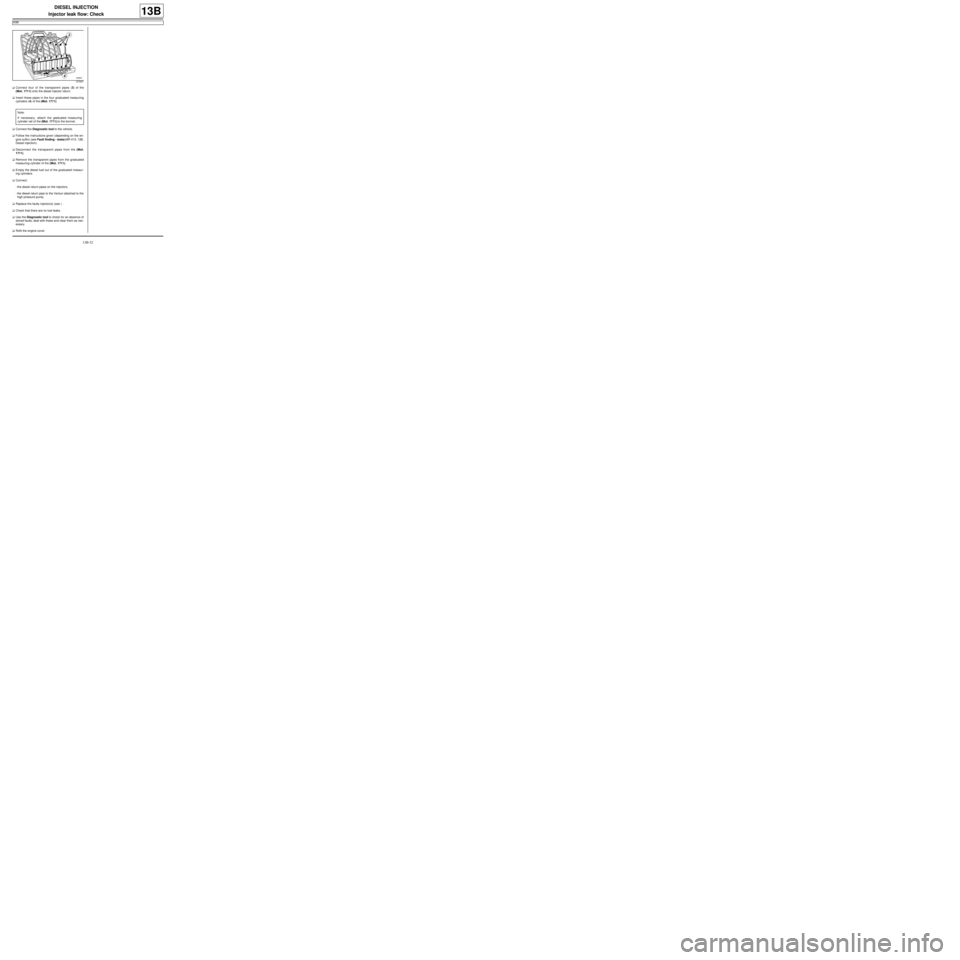
aConnect four of the transparent pipes (3) of the
(Mot. 1711) onto the diesel injector return.
aInsert these pipes in the four graduated measuring
cylinders (4) of the (Mot. 1711).
aConnect the Diagnostic tool to the vehicle.
aFollow the instructions given (depending on the en-
gine suffix) (see Fault finding - tests)(MR 413, 13B,
Diesel injection).
aDisconnect the transparent pipes from the (Mot.
1711).
aRemove the transparent pipes from the graduated
measuring cylinder of the (Mot. 1711).
aEmpty the diesel fuel out of the graduated measur-
ing cylinders.
aConnect:
-the diesel return pipes on the injectors,
-the diesel return pipe to the Venturi attached to the
high pressure pump.
aReplace the faulty injector(s) (see ) .
aCheck that there are no fuel leaks.
aUse the Diagnostic tool to check for an absence of
stored faults; deal with these and clear them as nec-
essary.
aRefit the engine cover.
107637
Note:
If necessary, attach the graduated measuring
cylinder rail of the (Mot. 1711) to the bonnet.
Page 420 of 652
14A-2
ANTIPOLLUTION
Fuel vapour recirculation circuit: Operating diagram
D4F or D7F
14A
D4F, and 772 – D7F
97393-1
(1) Inlet distributor
(2) Fuel vapour absorber bleed
solenoid valve
(3) Petrol vapour absorber
(4) Tank
(5) Fresh air vent
D4F, and 780 or 782
121923
(1) Inlet distributor
(2) Fuel vapour absorber bleed
solenoid valve
(3) Petrol vapour absorber
(4) Tank
(5) Fresh air vent
(6) Anti-retur n valve
(7) Turbocharger
(8) Air filter unit
(9) Air filter box air outlet pipe
Page 421 of 652

14A-3
ANTIPOLLUTION
Fuel vapour recirculation circuit: Check
D4F or D7F
14A
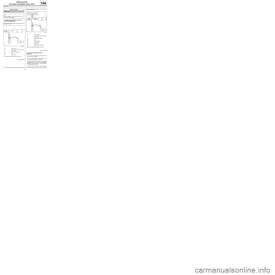
I - CHECKING THE OPERATION OF THE FUEL
VAPOUR ABSORBER BLEED
aCheck the condition of the pipes to the tank.aCheck the condition of the pipes to the tank.
II - FUEL VAPOUR ABSORBER BLEED
CONDITIONS
aThe fuel vapour absorber bleed solenoid valve is
controlled by the computer.
During « on board diagnostic » fault finding, fuel va-
pour absorber bleeding is not authorised.
The opening cyclic ratio of the fuel vapour absorber
bleed solenoid valve can be viewed on the Diagnos-
tic tool by reading parameter « Fuel vapour absorb-
er bleed solenoid valve OCR » .
The solenoid valve is closed for a value below 1.2%. Equipment required
Diagnostic tool
Note:
Incorrect operation of the system may result in
rough idle or engine stalling.
D4F, and 772 – D7F
97393-1
(1) Inlet distributor
(2) Fuel vapour absorber bleed
solenoid valve
(3) Petrol vapour absorber
(4) Tank
(5) Fresh air vent
D4F, and 780 or 782
121923
(1) Inlet distributor
(2) Fuel vapour absorber bleed
solenoid valve
(3) Petrol vapour absorber
(4) Tank
(6) Anti-retur n valve
(7) Turbocharger
(8) Air filter unit
(9) Air filter box air outlet pipe
Page 422 of 652

14A-4
ANTIPOLLUTION
Fuel vapour absorber: Removal - Refitting
D4F or D7F or K4M, and TECHNICAL REG: GERMANY or TECHNICAL REG: AUSTRIA or TECHNICAL REG:
BALKANS or TECHNICAL-LEGISLATIVE BELGIUM or TECHNICAL REG: BOSNIA or TECHNICAL REG:
CYPRUS-MALTA or CZECH REP AND SLOVAKIA or TECHNICAL REG: DENMARK or TECHNICAL REG: DOM
(FRENCH OVERSEAS SUBDIVISION) or TECHNICAL REG: SPAIN or TECHNICAL REG: FINLAND or
TECHNICAL REG: FRANCE or TECHNICAL REG: GREAT BRITAIN or TECHNICAL REG: GREECE or
TECHNICAL-LEGISLATIVE HOLLAND or TECHNICAL REG: HUNGARY or TECHNICAL REG: IRELAND or
TECHNICAL REG: ICELAND or TECHNICAL REG: ISRAEL or TECHNICAL REG: ITALY or TECHNICAL REG:
JAPAN or TECHNICAL REG: NORTH or TECHNICAL REG: NORWAY or TECHNICAL REG: POLAND or
TECHNICAL REG: PORTUGAL or TECHNICAL REG: SLOVENIA or TECHNICAL REG: SWEDEN or TECHNICAL
REG: SWITZERLAND or TECHNICAL REG: TOM (FRENCH OVERSEAS TERRITORIES)
14A
REMOVAL
I - REMOVAL PREPARATION OPERATION
aPosition the vehicle on a two-post lift (see Vehicle:
Towing and lifting) (02A, Lifting equipment).
aDisconnect the battery (see Battery: Removal - Re-
fitting) (80A, Battery).
II - REMOVAL OPERATION
aUnclip:
-the fuel filter on the fuel vapour absorber in the di-
rection of the arrow (1) ,
-the fuel vapour absorber in the direction of the ar-
row (2) . IMPORTANT
During this oper ation, be sure to:
-refrain from smoking or bringing red hot objects
close to the working area,
-be careful of fuel splashes when disconnecting the
union.
IMPORTANT
Wear goggles with side protectors for this opera-
tion.
IMPORTANT
Wear leaktight gloves (Nitrile type) for this opera-
tion.
WARNING
To avoid any corrosion or damage, protect the
areas on which fuel is likely to run.
WARNING
Keep the pipe unions away from contaminated
areas.
WARNING
To prevent impurities from entering the circuit, place
protective plugs on all fuel circuit components
exposed to the open air.
D4F or D7F
120513
Page 423 of 652

14A-5
ANTIPOLLUTION
Fuel vapour absorber: Removal - Refitting
D4F or D7F or K4M, and TECHNICAL REG: GERMANY or TECHNICAL REG: AUSTRIA or TECHNICAL REG:
BALKANS or TECHNICAL-LEGISLATIVE BELGIUM or TECHNICAL REG: BOSNIA or TECHNICAL REG:
CYPRUS-MALTA or CZECH REP AND SLOVAKIA or TECHNICAL REG: DENMARK or TECHNICAL REG: DOM
(FRENCH OVERSEAS SUBDIVISION) or TECHNICAL REG: SPAIN or TECHNICAL REG: FINLAND or
TECHNICAL REG: FRANCE or TECHNICAL REG: GREAT BRITAIN or TECHNICAL REG: GREECE or
TECHNICAL-LEGISLATIVE HOLLAND or TECHNICAL REG: HUNGARY or TECHNICAL REG: IRELAND or
TECHNICAL REG: ICELAND or TECHNICAL REG: ISRAEL or TECHNICAL REG: ITALY or TECHNICAL REG:
JAPAN or TECHNICAL REG: NORTH or TECHNICAL REG: NORWAY or TECHNICAL REG: POLAND or
TECHNICAL REG: PORTUGAL or TECHNICAL REG: SLOVENIA or TECHNICAL REG: SWEDEN or TECHNICAL
REG: SWITZERLAND or TECHNICAL REG: TOM (FRENCH OVERSEAS TERRITORIES)
14A
aUnclip the fuel vapour absorber in the direction of
the arrow (3) .
aDisconnect the fuel vapour absorber pipes.
aRemove the fuel vapour absorber.
REFITTING
I - REFITTING OPERATION
aRefit the fuel vapour absorber.
aConnect the fuel vapour absorber pipes.
aClip on:
-the fuel vapour absorber,-the fuel filter on the fuel vapour absorber.
aClip on the fuel vapour absorber.
II - FINAL OPERATION
aConnect the battery (see Battery: Removal - Refit-
ting) (80A, Battery). K4M
131771
D4F or D7F
K4M