2009 RENAULT TWINGO RS battery
[x] Cancel search: batteryPage 4 of 101

38C -4V3 MR-413-X44-38C050$010.mif
ANTI-LOCK BRAKING SYSTEM
Fault finding – Introduction
Bosch 8.1 ESP
Vdiag No.: 05
38C
4. FAULT FINDING PROCEDURE
Check the battery charge and
condition
Print the system fault finding log
(available on CLIP)
Connect CLIP
Refer to ALP No. 1
Read the faults
Deal with present faults
Deal with stored faults
Conformity check
Use fault finding charts (ALPs)
Dialogue with
computer?
Faults
present
The cause is
still present
The cause is
still presentThe cause is
still present
Contact the Techline with the
completed fault finding log
NO
NONO
NO NO
YES
YES
YES
Fault
solvedFault
solved Fault
solved
Page 8 of 101

38C -8V3 MR-413-X44-38C050$010.mif
ANTI-LOCK BRAKING SYSTEM
Fault finding – Introduction
Bosch 8.1 ESP
Vdiag No.: 05
38C
5. FAULT FINDING LOG
You will always be asked for this log:
–when requesting technical assistance from the Techline,
–when requesting approval before replacing parts for which approval is compulsory,
–to be attached to monitored parts for which reimbursement is requested. The log is needed for warranty
reimbursement, and enables better analysis of the parts removed.
6. SAFETY INSTRUCTIONS
Safety rules must be observed during any work on a component to prevent any material damage or personal injury:
–check the battery voltage to avoid incorrect operation of computer functions,
–use the proper tools.
It is forbidden to carry out a road test with the diagnostic tool in dialogue with the ECU because the ABS and
Electronic Brake Distribution functions are deactivated. Braking pressure is identical on both vehicle axles
(risk of a spin under heavy braking).IMPORTANTIMPORTANT
All faults involving a complex system call for thorough diagnostics with the appropriate tools. The
FAULT FINDING LOG, which should be completed during the fault finding procedure, ensures a
record is kept of the procedure carried out. It is an essential document when consulting the
manufacturer.
IT IS THEREFORE ESSENTIAL THAT THE FAULT FINDING LOG IS FILLED OUT EVERY TIME IT IS
REQUESTED BY TECHLINE OR THE WARRANTY RETURNS DEPARTMENT.
Page 11 of 101

38C-11V3 MR-413-X44-38C050$030.mif
38C
Bosch 8.1 ESP
Vdiag No.: 05
Number Description
1Computer/hydraulic unit assembly
2Steering wheel angle
3Torque setpoint on the engine management computer
4Sequential gearbox operating phase (if fitted)
5Instrument panel
6Diagnostic socket
7 UCH
8Vehicle speed wire
9Brake light control relay
10Combined sensor: lateral acceleration and yaw speed
11Brake disc with instrumented bearing target
12Wheel speed sensor
13Battery
14Traction control deactivation button (Only on RS version)
15Brake switch
Electric circuit
Hydraulic circuit
Private multiplex line
Vehicle multiplex line
ANTI-LOCK BRAKING SYSTEM
Fault finding – Functional diagram
Page 14 of 101

38C-14V3 MR-413-X44-38C050$060.mif
38C
Bosch 8.1 ESP
Vdiag No.: 05
Fault finding warning lights programming
Instrument panel warning light Meaning
Brake faultsABS system ESP SERVICE STOP"Brake limiter", ABS, and
ESP functions not working
ABS system ESP SERVICEESP and ABS functions not
working, "brake limiter"
operational
ESP SERVICEESP function not working, ABS
and "brake limiter"
operational
ESP
"Wheel traction control"
function deactivated by fault
finding orESPmomentarily
disco nnected a fter the battery is
disconnected
Brake faults
flashing
at 2 H z (slowly)ABS flashing
at 2 Hz
(slowly)ESP flashing
at 2 Hz (slowly)ESP computer in fault finding
mode
ESP flashing
at 8 Hz
(quickly)ESP or "wheel traction control"
or "anti-lock brake system on
engine torque control" active
ABS flashing
at 8 Hz
(quickly)Tachometric index not
programmed
Brake faults ABS systemESP flashing
at 8 Hz
(quickly)SERVICE STOPVehicle variant not
programmed
Brake faultsABS flashing
at 8 Hz
(quickly)ESP flashing
at 8 Hz
(quickly)STOPVehicle option and tachometric
index not programmed
Note:
The STOP warning light is always accompanied by a single audible warning (1 beep).
ANTI-LOCK BRAKING SYSTEM
Fault finding – Defect and safe modes
Page 19 of 101

38C-19
AFTER REPAIRClear the computer fault memory.
Carry out a road test followed by another check with the diagnostic tool
If the fault is still present, contact the Techline.
V3 MR-413-X44-38C050$101.mif
38C
Bosch 8.1 ESP
Vdiag No.: 05
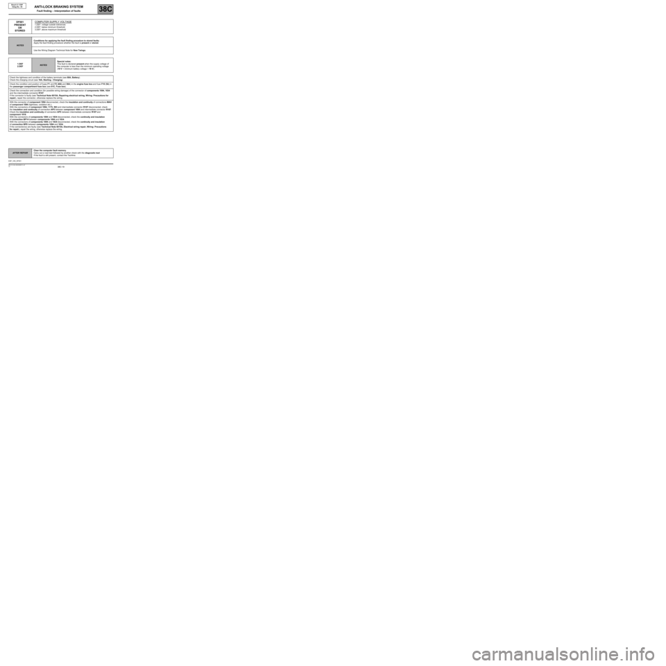
DF001
PRESENT
OR
STOREDCOMPUTER SUPPLY VOLTAGE
1.DEF: voltage outside tolerances
2.DEF: below minimum threshold
3.DEF: above maximum threshold
NOTESConditions for applying the fault finding procedure to stored faults:
Apply the fault finding procedure whether the fault is present or stored.
Use the Wiring Diagram Technical Note for New Twingo.
1.DEF
2.DEF
NOTESSpecial notes:
This fault is declared present when the supply voltage of
the computer is less than the minimum operating voltage
(10 V < minimum battery voltage < 16 V).
Check the tightness and condition of the battery terminals (see 80A, Battery).
Check the charging circuit (see 16A, Starting - Charging).
Check the condition and position of fuses F1 and F2 (40A and 30A) in the engine fuse box and fuse F10 (5A) in
the passenger compartment fuse box (see 81C, Fuse box).
Check the connection and condition (for possible wiring damage) of the connector of components 1094, 1834
and the intermediate connector R107.
If the connector is faulty (see Technical Note 6015A, Repairing electrical wiring, Wiring: Precautions for
repair), repair the connector, otherwise replace the wiring.
With the connector of component 1094 disconnected, check the insulation and continuity of connections MAH
of component 1094 (tightness, oxidation etc.).
With the connectors of component 1094, 1175, 583 and intermediate connector R107 disconnected, check
the insulation and continuity of connection AP5 between component 1094 and intermediate connector R107.
Check the insulation and continuity of connection AP5 between intermediate connector R107 and
component 1016.
With the connectors of components 1094 and 1834 disconnected, check the continuity and insulation
of connection BP14 between components 1094 and 1834.
With the connectors of components 1094 and 1834 disconnected, check the continuity and insulation
of connection BP8 between components 1094 and 1834.
If the connection(s) are faulty (see Technical Note 6015A, Electrical wiring repair, Wiring: Precautions
for repair), repair the wiring, otherwise replace the wiring.
ANTI-LOCK BRAKING SYSTEM
Fault finding – Interpretation of faults
ESP_V05_DF001
Page 20 of 101

38C-20
AFTER REPAIRClear the computer fault memory.
Carry out a road test followed by another check with the diagnostic tool
If the fault is still present, contact the Techline.
V3 MR-413-X44-38C050$101.mif
ANTI-LOCK BRAKING SYSTEM
Fault finding – Interpretation of faults38C
Bosch 8.1 ESP
Vdiag No.: 05
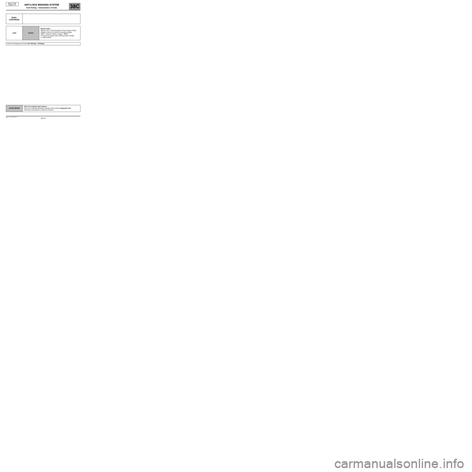
DF001
CONTINUED
3.DEFNOTESSpecial notes:
Special notes: This fault appears if the computer supply
voltage is above the maximum operating voltage
(16 V < maximum battery voltage < 19.6 V).
This fault may appear when starting using a charger
or a 24 V battery.
Check the charging circuit (see 16A, Starting - Charging).
Page 27 of 101

38C-27
AFTER REPAIRClear the computer fault memory.
Carry out a road test followed by another check with the diagnostic tool
If the fault is still present, contact the Techline.
V3 MR-413-X44-38C050$101.mif
ANTI-LOCK BRAKING SYSTEM
Fault finding – Interpretation of faults38C
Bosch 8.1 ESP
Vdiag No.: 05
DF011
PRESENT
OR
STOREDSOLENOID VALVE SUPPLY
DEF: Abnormal voltage
NOTESConditions for applying the fault finding procedure to stored faults:
Apply the fault finding procedure whether the fault is present or stored.
Use the Wiring Diagram Technical Note for New Twingo.
Check the tightness and condition of the battery terminals (see 80A, Battery).
Check the charging circuit (see 16A, Starting - Charging).
Check the condition and position of fuse F2 (30A) in the engine fuse box.
Check the connection and condition (possible wiring damage) of the connector of component 1094.
If the connector is faulty (see Technical Note 6015A, Repairing electrical wiring, Wiring: Precautions
for repair), repair the connector, otherwise replace the wiring.
With the connector of component 1094 disconnected, check the insulation and continuity of connections MAH
of component 1094 (tightness, oxidation, etc.).
With the connectors of components 1094 and 1834 disconnected, check the continuity and insulation
of connection BP8 between components 1094 and 1834.
If the connection or connections are faulty (see Technical Note 6015A, Electrical wiring repair, Wiring:
Precautions for repair), repair the connectors or wiring, otherwise replace the wiring.
ESP_V05_DF011
Page 28 of 101

38C-28
AFTER REPAIRClear the computer fault memory.
Carry out a road test followed by another check with the diagnostic tool
If the fault is still present, contact the Techline.
V3 MR-413-X44-38C050$101.mif
ANTI-LOCK BRAKING SYSTEM
Fault finding – Interpretation of faults38C
Bosch 8.1 ESP
Vdiag No.: 05
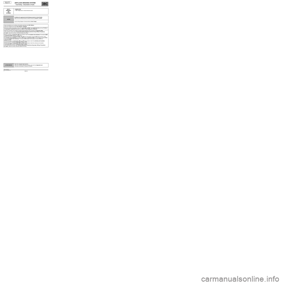
DF017
PRESENT
OR
STOREDCOMPUTER
1. DEF: Supply fault or internal electronic fault
NOTESConditions for applying the fault finding procedure to stored faults:
Apply the fault finding procedure whether the fault is present or stored.
Use the Wiring Diagram Technical Note for New Twingo.
Check the tightness and condition of the battery terminals (see 80A, Battery).
Check the charging circuit (see 16A, Starting - Charging).
Check the condition and position of fuses F1 and F2 (40A and 30A) in the engine fuse box and fuse F10 (5A) in
the passenger compartment fuse box (see MR413, Fault finding, 81C, Fuse box).
Check the connection and condition (possible wiring damage) of the connector of component 1094.
If the connector is faulty (see Technical Note 6015A, Repairing electrical wiring, Wiring: Precautions
for repair), repair the connector, otherwise replace the wiring.
With the connector of component 1094 disconnected, check the insulation and continuity of connections MAH
of component 1094 (tightness, oxidation etc.).
With the connectors of component 1094, 1175, 583 and intermediate connector R107 disconnected, check
the insulation and continuity of connection AP5 between component 1094 and intermediate connector R107.
Check the insulation and continuity of connection AP5 between intermediate connector R107 and
component 1016.
With the connectors of components 1094 and 1834 disconnected, check the continuity and insulation
of connection BP14 between components 1094 and 1834.
With the connectors of components 1094 and 1834 disconnected, check the continuity and insulation
of connection BP8 between components 1094 and 1834.
If the connection(s) are faulty (see Technical Note 6015A, Electrical wiring repair, Wiring: Precautions
for repair), repair the wiring, otherwise replace the wiring.
ESP_V05_DF017