2009 RENAULT SCENIC ABS
[x] Cancel search: ABSPage 197 of 273

DIESEL INJECTION
Fault finding – Interpretation of statuses13B
13B - 197V3 MR-372-J84-13B250$630.mif
EDC16
PROGRAM NO.: C1
Vdiag No.: 51
1
STATUS 7
ET415
(CONTINUED 3)
STATUS 6
Gear lever in neutral (manual gearbox) or the neutral position (automatic gearbox)
Status ET415 becomes STATUS 6, when driving with cruise control active (ET042:
Cruise control/speed limiter: CRUISE CONTROL) and:
- If the driver puts the gear lever in neutral position on a manual gearbox without
declutching or,
- if the gear lever is in neutral on an automatic gearbox.
This deactivates cruise control.
Reinitialise status ET415 on the injection computer by running command RZ007
“Fault memory”.
If status ET415 becomes STATUS 6 without shifting the gear lever into neutral on a
manual gearbox without declutching, or into neutral on an automatic transmission, test
the ABS computer and check the configuration of the tyre size stored in the computer. If
the configuration is correct, contact the Techline.
Inconsistency between the request and the vehicle speed
Status ET415 becomes STATUS 7 if the computer detects too great a difference
between the speed requested by the driver and the vehicle speed.
This could occur when driving with cruise control active (ET042 Cruise control/ speed
limiter: CRUISE CONTROL) and when there is a significant difference.
This inconsistency deactivates cruise control.
Reinitialise status ET415 on the injection computer by running command RZ007
“Fault memory”.
If status ET415 changes to STATUS 7 where there is no significant difference in the
levels, contact the Techline.
AFTER REPAIRSwitch off the ignition and carry out a road test followed by a test with the diagnostic
tool.
Page 198 of 273

DIESEL INJECTION
Fault finding – Interpretation of statuses13B
13B - 198V3 MR-372-J84-13B250$630.mif
EDC16
PROGRAM NO.: C1
Vdiag No.: 51
1
STATUS 9
ET415
(CONTINUED 4)
STATUS 8
Automatic transmission in defect mode.
Status ET415 becomes STATUS 8, when driving with cruise control active (ET042:
Cruise control/speed limiter: CRUISE CONTROL) and if the automatic transmission
is in defect mode.
This signal is conveyed on the multiplex line and deactivates the cruise control.
Carry out a multiplex network test, then run fault finding on the automatic transmission
computer.
Deal with any present or stored faults (see 23A, Automatic transmission,
interpretation of faults).
Clear the automatic transmission computer memory by running command RZ007 “Fault
memory”.
Reinitialise status ET415 on the injection computer by running command RZ007
“Fault memory”.
If status 8 continues, contact the Techline.
Vehicle speed monitoring.
Status ET415 becomes STATUS 9 if the vehicle speed received by the computer is
invalid or absent.
This signal is conveyed on the multiplex line and deactivates the cruise control.
Carry out a multiplex network test, then run fault finding on the ABS computer.
Deal with any present or stored faults (see 38C, Anti-lock braking system,
interpretation of faults).
Reinitialise status ET415 on the injection computer by running command RZ007
“Fault memory”.
If status 9 continues, contact the Techline.
AFTER REPAIRSwitch off the ignition and carry out a road test followed by a test with the diagnostic
tool.
Page 215 of 273

DIESEL INJECTION
Fault finding – Interpretation of commands13B
13B -215V3 MR-372-J84-13B250$765.mif
EDC16
PROGRAM No: C1
Vdiag No.: 51
AC001
PREHEATING UNIT
NOTESThis command is only carried out if the fault DF025 Preheating unit fault finding
connection, or DF017 Preheating unit control circuit is present or stored and if no
other fault is present.
Refer to the Wiring diagrams Technical Note for the vehicle to locate the fuses and
relays concerned.
Connect the diagnostic tool and turn on the ignition.
With the preheating unit connected:
–connect the negative terminal of the voltmeter to track 8 of the preheating unit,
–connect the positive terminal of the voltmeter to the + 12 V battery,
–run command AC001 Preheating unit.
if the voltmeter does not indicate the battery voltage while the command is running (ten 1 second ON/OFF cycles):
1Check the condition of the preheating unit supply fuse F01 (70A).
Replace it if necessary.
2Check the following connections for continuity and the absence of interference resistance:
Injection computer connector C track E2 track 8 of the preheating unit connector
Injection computer connector C track A4 Track 3 of the preheating unit connector
Repair if necessary.
3Check the connections on the pre-postheating unit, heater plugs and injection computer.
Repair if necessary.
4Measure the resistance of the heater plugs. If this resistance is greater than 2 Ω replace the faulty plug(s).
5Check the continuity and absence of interference resistance between:
preheating unit track 1 cylinder 3 heater plug
preheating unit track 2 cylinder 1 heater plug
preheating unit track 6 cylinder 4 heater plug
preheating unit track 7 cylinder 2 heater plug.
6Then check for + 12 V supply on track 4 of the preheating relay connector.
If the fault is still present, replace the preheating unit.
EDC16_V51_AC001
Page 218 of 273
DIESEL INJECTION
Fault finding – Interpretation of commands13B
13B -218V3 MR-372-J84-13B250$765.mif
EDC16
PROGRAM No: C1
Vdiag No.: 51
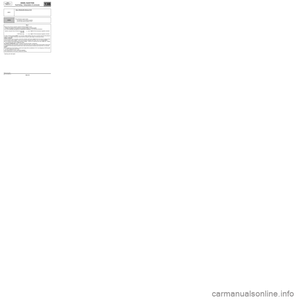
* Opening cyclic ratio signalAC011
RAIL PRESSURE REGULATOR
NOTESThis command is used to check:
–the operation of the pressure regulator,
–and the high pressure injection circuit.
Step 1
Measure the pressure regulator resistance between tracks 1 and 2.
–Replace the regulator if its resistance is not approximately: 3 Ω ± 0.5 at 20˚C.
Check the continuity and absence of interference resistance of the following connections:
Injection computer brown 48-track connector B,
track M4track 2 of the rail pressure regulator connector
+ 12 V after relaytrack 1 of the rail pressure regulator connector
If, when running command AC011, you can hear a slight whistling noise and a crunching noise from the pressure
regulator, go to step 2. Otherwise, ensure that the computer output stage is functioning correctly:
Using a voltmeter:
With the solenoid valve connected, connect the voltmeter earth lead to track 2 of the fuel pressure solenoid valve
and the positive cable to track 1. Clear any fuel pressure solenoid valve faults, then run command AC011:
●The voltmeter should display two successive voltages: ~ 2.5 V for an opening cyclic ratio of 20% then ~ 8.75 V
for an opening cyclic ratio* of 70% (ten cycles).
Or using an oscilloscope (range 5 V/division and with time base 1 ms/division):
With the solenoid valve connected, connect the oscilloscope earth to the battery earth and the positive contact point
on track 2 of the fuel pressure solenoid valve; clear any fuel pressure solenoid valve faults then run command
AC011:
●the oscilloscope should display a square wave signal with an amplitude of 12.5 V at a frequency of 185 Hz (with
an OCR* passing from 20 to 70%).
If the measurement is correct, replace the regulator.
If the measurement is not correct, contact the Techline.
EDC16_V51_AC011
Page 220 of 273
DIESEL INJECTION
Fault finding – Interpretation of commands13B
13B -220V3 MR-372-J84-13B250$765.mif
EDC16
PROGRAM No: C1
Vdiag No.: 51
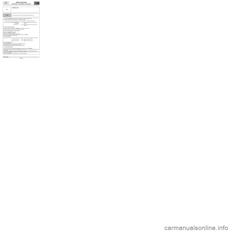
AC012
DAMPER VALVE
NOTESThis command allows you to check the operation of the damper valve.
–Measure the resistance of the damper valve solenoid valve between tracks 1 and 2.
Replace the solenoid valve if the resistance is not: 46 ± 3 Ω at + 25˚C.
–Check for continuity and for the absence of interference resistance on the following connections:
Injection computer, brown 48-track connector
B, track M1track 1 of the damper valve solenoid valve
connector
+ 12 V after relaytrack 2 of the damper valve solenoid valve
connector
A) Engine running at idle speed
Make sure that there is a pressure of ~ 900 mbar on the solenoid valve inlet hose.
Make the necessary repairs (pressure circuit conformity and seal).
B) With the vehicle ignition on, engine stopped
Make sure the damper valve is open.
If not, clean or replace the air vent unit.
Disconnect the solenoid valve inlet and outlet hoses,
Connect a vacuum pump to the inlet union and apply a pressure of ~900 mbar
If there is a leak, replace the solenoid valve.
Run command AC012.
Otherwise, with the solenoid valve connected, check operation of the computer output stage with a voltmeter:
Voltmeter earth cabletrack 1 of the solenoid valve
Voltmeter positive leadtrack 2 of the solenoid valve
Clear any solenoid valve faults,
Run command AC012.
The voltmeter should display ten ON-OFF cycles (8.75 V then 2.5 V).
If the measurement is correct, replace the solenoid valve.
If the measurement does not show any lights, contact the Techline.
C) Vehicle with ignition off
Connect a vacuum pump to the flap control diaphragm and apply a pressure of ~900 mbar:
If the diaphragm does not maintain the negative pressure, replace the air vent unit (the diaphragm cannot be
disconnected).
If the diaphragm maintains the vacuum and the flap does not operate, clean or replace the air vent unit.
If the diaphragm maintains the underpressure and the valve operates, then operate it several times to ensure
that there is no blockage.
Check for clogging of the air vent unit and its valve, and clean if necessary.
EDC16_V51_AC012
Page 221 of 273
DIESEL INJECTION
Fault finding – Interpretation of commands13B
13B -221V3 MR-372-J84-13B250$765.mif
EDC16
PROGRAM No: C1
Vdiag No.: 51
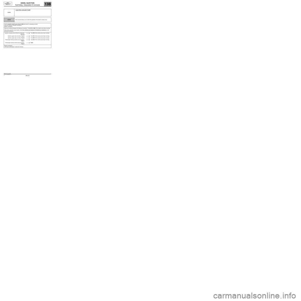
AC195
ELECTRIC COOLANT PUMP
NOTESThis command allows you to check the operation of the electric coolant pump.
Test the electric coolant pump relay (A 20A) and check it is operating correctly.
Check the injection computer connections.
Repair if necessary.
Check the continuity between the following connections: Tracks B1 and B5 of the coolant pump relay mounting.
If the checks yield the correct results, check the continuity and absence of interference resistance on the
following connections:
Injection computer brown 48-track connector B,
track H4Track B2 of the coolant pump relay mounting
Injection supply relay mounting, Track 5Track B1 of the coolant pump relay mounting
Injection supply relay mounting, Track 5Track B5 of the coolant pump relay mounting
Turbocharger bearing coolant pump connector,
Track 1Track B3 of the coolant pump relay mounting
Turbocharger bearing coolant pump connector,
Track 2Earth
Repair if necessary.
If the fault is still present, contact the Techline.
EDC16_V51_AC195
Page 223 of 273
DIESEL INJECTION
Fault finding – Fault Finding Chart13B
13B -223V3 MR-372-J84-13B250$855.mif
EDC16
PROGRAM No.: C1
Vdiag No.: 51DIESEL INJECTION
Fault finding – Fault Finding Chart
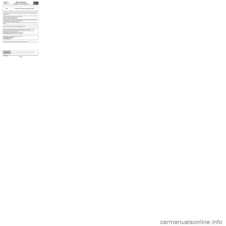
ALP1 No dialogue with engine management computer
Try to establish dialogue with a computer on another vehicle to make sure that the diagnostic tool is not faulty.
Check the battery voltage and make the necessary adjustments to obtain a correct voltage (9.5 V < Battery
voltage < 17.5 V).
If the tool is not at fault, and dialogue cannot be established with any other computer on the same vehicle, the cause
could be a faulty computer interfering on the multiplex network.
disconnect the engine management computer.
try to establish dialogue with another computer.
if the fault is still present, reconnect the computer and proceed by elimination by successively disconnecting all the
following computers (according to wiring diagram and equipment): air conditioning, airbag, abs and esp, uch,
instrument panel, central communication unit, proximity sensor.
Try to establish dialogue after disconnecting each line:
if, after a disconnection, you manage to establish dialogue, perform the fault finding procedure for the relevant
computer.
perform fault finding on the multiplex network using the diagnostic tool.
Check for the presence and the condition of the injection fuses on the UPC, and/or the engine fuse box.
check the connection of the computer connectors and the condition of its connections.
Check the injection computer earths (quality, oxidation, earth bolts secure on the battery terminal).
Check that the supply to the computer is correct:
Earth on tracks H1, G4 and H4 of black 32-track connector A.
+ after ignition feed on track D1 of black 32 track connector A.
Check that the power supply to the diagnostic socket is correct:
+ before ignition feed on track 16.
+ after ignition feed on track 1.
Earth on tracks 4 and 5.
If dialogue has still not been established after these checks, contact the techline.
AFTER REPAIRCarry out a road test followed by a complete check with the diagnostic tool.
EDC16_V51_ALP1
Page 229 of 273
DIESEL INJECTION
Fault finding – Fault Finding Chart13B
13B -229V3 MR-372-J84-13B250$855.mif
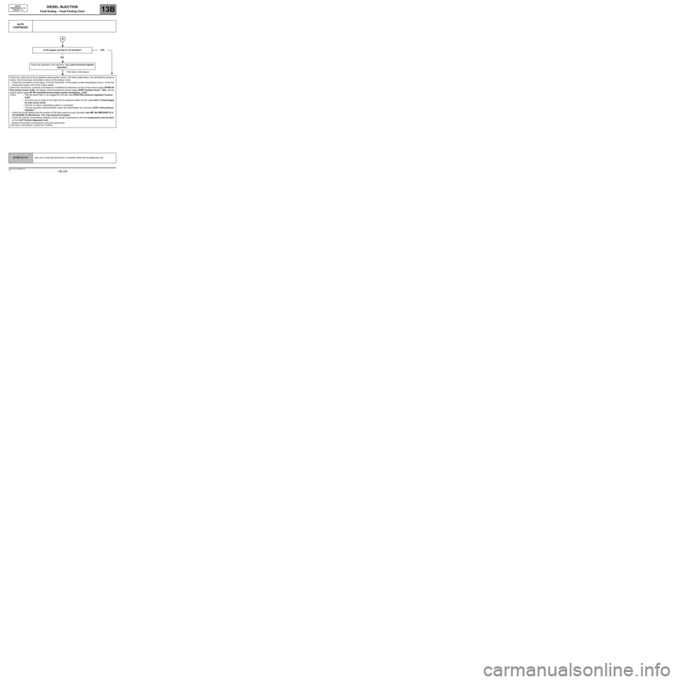
ALP4
CONTINUED
Is the engine running on all cylinders?
NO
Check the operation of the injectors: apply test 8 Incorrect injector
operation.
If the fault is still present
Check the conformity of the accelerator pedal position sensor, the brake pedal sensor, the atmospheric pressure
sensor, the exhaust gas recirculation valve and the damper valve.
–Check the consistency of the signal: of the air flowmeter, of the engine coolant temperature sensor, of the fuel
temperature sensor and of the engine speed.
Check the connections, continuity and absence of interference resistance on the air flow sensor (apply DF056 Air
flow sensor circuit, 2.def), the engine coolant temperature sensor (apply DF001 Coolant circuit, 1.def), and the
engine speed (apply DF195 Camshaft sensor/engine speed consistency, 2.def).
Check: – That the diesel filter is not clogged (for the test, see DF053 Rail pressure regulation function
2.def).
–That there are no leaks on the high and low pressure diesel circuits: apply test 3 Turbocharged
air inlet circuit check.
–That the oil vapour rebreathing system is connected.
–The flow regulator (blocked/seized, apply the interpretation for command: AC011 Rail pressure
regulator).
–Check the timing setting (and the position of the high pressure pump sprocket) (see MR 364 (MEGANE II) or
370 (SCENIC II), Mechanical, 11A, Top and front of engine).
–Check the cylinder compressions (balance of the cylinder compressions with the Compression test function
on the CLIP Technic diagnostic tool).
–Measure the engine compressions using the special tool.
If the fault is still present, contact the Techline.YES
EDC16
PROGRAM No.: C1
Vdiag No.: 51
AFTER REPAIRcarry out a road test followed by a complete check with the diagnostic tool.