2009 OPEL AGILA clock
[x] Cancel search: clockPage 51 of 153

5-1Instruments and controls
Instruments and
controlsSteering wheel adjustment
To adjust steering wheel 3, pull lever
forwards, adjust height, push lever
back and engage.
Adjust steering wheel only with
vehicle stationary and steering
column lock released.
Push the lever firmly backwards to
ensure that the steering wheel is
locked in position.
Steering wheel mounted
remote control 3
The functions of the Infotainment
system can be operated with the
buttons on the steering wheel.
Further information 3 7-2. Horn j .................................... 5-2
Windscreen wipers................ 5-2
Windscreen washer system .. 5-3
Rear window wiper/washer ... 5-3
Clock ..................................... 5-3
Outside temperature 3 .......... 5-4
Power outlets ........................ 5-4
Cigarette lighter ) 3 ............... 5-5
Ashtrays 3 ............................. 5-5
Warning lights, gauges and
indicators ............................ 5-5
Transmission display 3 ......... 5-7
Control indicators .................. 5-8
Warning chimes .................... 5-13
Service interval display 3 ...... 5-14
Engine oil life monitor 3......... 5-14
Trip computer 3 ..................... 5-14
Page 53 of 153

5-3Instruments and controls
Windscreen washer system
To activate, pull lever towards
steering wheel. Washer fluid is
sprayed onto the windscreen.
In vehicles with timed interval wipe
position INT 3, the wipers switch on
automatically at low speed if they are
not already activated.
Rear window wiper/washer
To activate wiper and washer, rotate
end of lever:
Washer fluid is sprayed on to rear
window when the end of the lever is
turned to position
f. When the lever
is released, it will spring back to the
ON/OFF position.Further information 3 10-5, 10-30,
10-31.
Clock
The time is shown in the odometer
display when the ignition is switched
on.
Correcting time
To set the clock, press and hold the
Öbutton for approx. 2 seconds; clock
display now in setting mode. f=Washer
ON = Wiper on
INT = Timed interval wipe 3
OFF = Wiper off
f=Washer
Minute display flashes.
Press Ö to set minutes.
Page 100 of 153

9-13 Driving and operating
The tank flap is opened by pulling up
the release lever located on the
outboard side of the driver’s seat.The fuel filler neck is located on the
left rear side of the vehicle.
To open fuel filler cap: turn it anti-
clockwise.
Fuel consumption,
CO
2emissions
Directive 80/1268/EEC (last changed
by 2004/3/EG) has applied for the
measurement of fuel consumption
since 1996.
The directive is oriented to actual
driving practices: Urban driving is
rated at approx.
1/3 and extra-urban
driving with approx. 2/3 (urban and
extra-urban consumption). Cold
starts and acceleration phases are
also taken into consideration.
The specification of CO
2 emission is
also a constituent of the directive.The figures given must not be taken
as a guarantee for the actual fuel
consumption of a particular vehicle.
All values are based on the EU base
model with standard equipment.
The calculation of fuel consumption
as specified by directive 2004/3/EG
takes account of the vehicle’s kerb
weight, ascertained in accordance
with these regulations. Optional
extras may result in slightly higher
fuel consumption and CO
2emission
levels than those quoted.
Fuel consumption, CO
2emissions
312-4.
Caution
Wipe off any overflowing fuel
immediately.
Page 108 of 153

10-8 Vehicle care
High beam and dipped beam
1. Remove headlamp protective
cover.
2. Detach plug connector from bulb.
3. Push retaining spring wire clip
forward and unhook it.
4. Remove bulb from reflector
housing and pull bulb straight out of
socket.
5. Insert new bulb by pushing in and
install in reflector housing.
6. Engage spring wire clip, and
reattach plug connector to bulb.7. Replace headlamp protective
cover.
Parking lamps
1. Remove headlamp protective
cover.
2. Remove parking lamp socket from
reflector housing.
3. Remove bulb (2) from socket by
pulling straight out.
4. Insert new bulb by pushing in.
5. Install parking lamp socket in
reflector housing.
6. Replace headlamp protective
cover.
Front turn signal lamps
1. Rotate bulb holder anti-clockwise
and remove from reflector housing.
2. Push bulb (1) into socket slightly,
rotate anti-clockwise and remove.
3. Insert new bulb and install bulb
holder in reflector housing by
rotating clockwise.
Front fog lamps 3
Access the rear of the fog lamp from
behind the front bumper.
1. Rotate bulb holder anti-clockwise
and remove from reflector housing.
Page 109 of 153

10-9Vehicle care
2. Remove bulb from socket by
pulling straight out.
3. Insert new bulb by pushing in.
4. Insert bulb holder in reflector
housing, rotate clockwise and
engage in position.
If the bulb is inaccessible, seek the
assistance of a workshop.
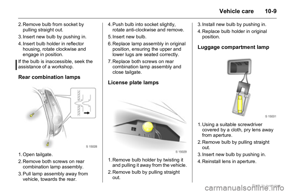
Rear combination lamps
1. Open tailgate.
2. Remove both screws on rear
combination lamp assembly.
3. Pull lamp assembly away from
vehicle, towards the rear.4. Push bulb into socket slightly,
rotate anti-clockwise and remove.
5. Insert new bulb.
6. Replace lamp assembly in original
position, ensuring the upper and
lower lugs are seated correctly.
7. Replace both screws on rear
combination lamp assembly and
close tailgate.
License plate lamps
1. Remove bulb holder by twisting it
and pulling it away from the vehicle.
2. Remove bulb by pulling straight
out.3. Install new bulb by pushing in.
4. Replace bulb holder in original
position.
Luggage compartment lamp
1. Using a suitable screwdriver
covered by a cloth, pry lens away
from aperture.
2. Remove bulb by pulling straight
out.
3. Insert new bulb by pushing in.
4. Reinstall lens in aperture.
Page 123 of 153

10-23Vehicle care
4. Attach the jack handle to the
wheel bolt wrench (as shown in
illustration) and insert hook end
of jack handle through jack eye.
Before positioning the jack, set it
to the necessary height by
rotating the jack handle
clockwise using the attached
wheel bolt wrench.5. Position jack at the front or rear
jacking point located nearest to
the wheel concerned so that the
jack claw spans the vertical
base. Make sure it is properly
positioned, ensuring the jacking
bar fits securely into the jack
head groove.
The jack base must be on the
ground directly below the jacking
point in a manner that prevents it
from slipping.6. Rotate jack handle clockwise
using the attached wheel bolt
wrench to raise vehicle.
Raise the vehicle until the wheel
is just clear of the ground.
7. Unscrew wheel bolts completely
by turning anti-clockwise and
wipe clean with a cloth.
Put wheel bolts somewhere
where the threads will not be
soiled.
Page 124 of 153

10-24 Vehicle care
Temporary spare wheel
The temporary spare wheel is
designed for use on your vehicle only.
Do not attempt to use the spare tyre
on a different wheel, or use a different
tyre on the spare wheel, as they will
not fit.
Ensure the temporary spare wheel is
inflated to the correct tyre pressure 3
12-8.The temporary spare wheel is located
in the luggage compartment and is
secured with a screw-in retainer.
To access the spare wheel, open
tailgate and pull up luggage
compartment floor carpet using the
central strap located near the tailgate
latch and hang the string on the hook
provided 3 4-4.
If equipped, remove the under floor
storage compartment 3 from the
luggage compartment by pulling it up
by the handle located near the
tailgate latch, to access the spare
wheel 3 4-4. 8. Remove wheel and install
spare wheel.
9. Screw on wheel bolts and
tighten slightly by hand until
wheel is held against the hub.
10. Apply a light coating of grease
to the cone of each wheel bolt.
Do not grease the threads.
11. Rotate jack handle anti-
clockwise using the attached
wheel bolt wrench to lower
vehicle to the ground.
12. Tighten wheel bolts to the
correct torque (85 Nm) in a
cross wise sequence, putting
the wheel bolt wrench on as far
as possible.
13. Stow replaced wheel in
luggage compartment.
14. Stow the warning triangle 3
and jacking equipment 3 4-5,
10-25.
Page 125 of 153

10-25Vehicle care
Remove the retainer by rotating it
anti-clockwise, and remove spare
wheel from the spare wheel well.
General information
If you use winter tyres 3, the spare
wheel may still be fitted with a
summer tyre.
If you use the spare wheel when it is
fitted with a summer tyre, the
vehicle's driveability may be affected,
especially on slippery road surfaces.
Obtain a replacement for the faulty
tyre as soon as possible, and have
the wheel balanced and fitted to the
vehicle.
�„Using a temporary spare wheel
may change the driving behaviour
of the vehicle, particularly if using
winter tyres3. Replace defective
tyre as quickly as possible, balance
wheel and fit to vehicle.
�„Fit only one temporary spare
wheel.
�„Do not drive faster than 80 km/h
(50 mph).
�„Take curves slowly.�„Do not use the temporary spare
wheel for a lengthy period.
�„Replace temporary spare wheel
with full specification wheel without
delay.
�„When temporary spare wheel is
fitted, do not take the vehicle
through an automatic car wash with
guide rails. The temporary spare
wheel may get caught on the rails,
causing damage to the tyre, wheel
and other vehicle parts.
�„Tyre chains are not permitted on
the temporary spare wheel.
�„If tyre chains are necessary after a
front wheel puncture, fit the
temporary spare wheel to the rear
and a rear wheel to the front. Check
tyre pressure and adjust if
necessary 3 12-8.Tools
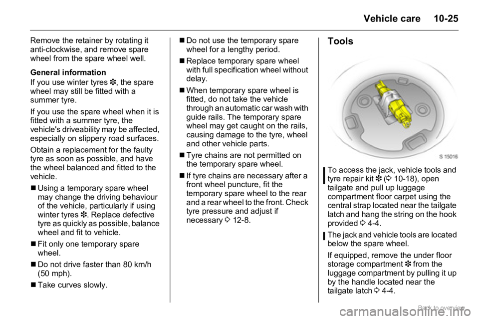
To access the jack, vehicle tools and
tyre repair kit 3 (3 10-18), open
tailgate and pull up luggage
compartment floor carpet using the
central strap located near the tailgate
latch and hang the string on the hook
provided 3 4-4.
The jack and vehicle tools are located
below the spare wheel.
If equipped, remove the under floor
storage compartment 3 from the
luggage compartment by pulling it up
by the handle located near the
tailgate latch 3 4-4.