2009 NISSAN TIIDA Schedule
[x] Cancel search: SchedulePage 3752 of 4331
MA
N
O P
PERIODIC MAINTENANCE
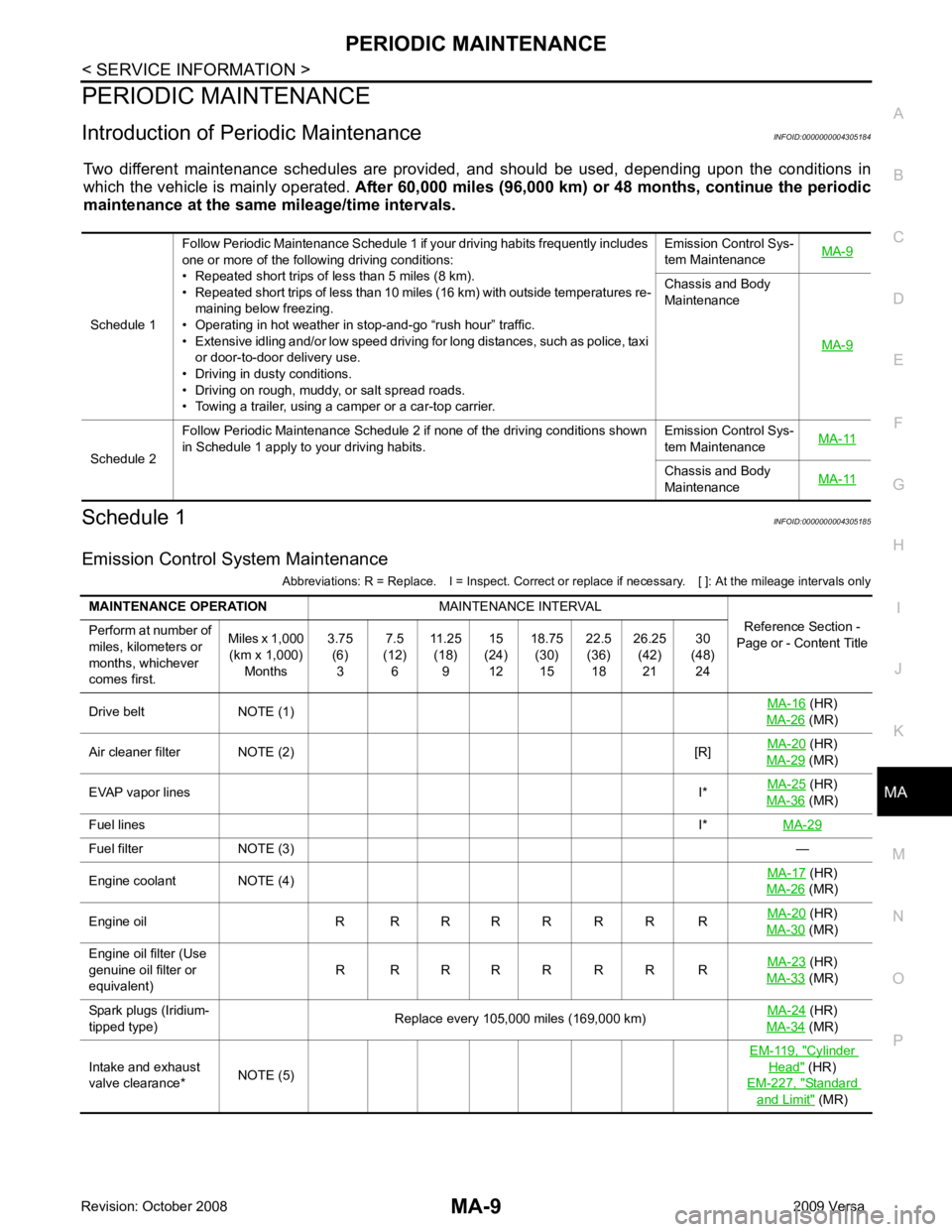
Introduction of Periodic Maintenance INFOID:0000000004305184
Two different maintenance schedules are provi ded, and should be used, depending upon the conditions in
which the vehicle is mainly operated. After 60,000 miles (96,000 km) or 48 months, continue the periodic
maintenance at the same mileage/time intervals.
Schedule 1 INFOID:0000000004305185
Emission Control System Maintenance Abbreviations: R = Replace. I = Inspect. Correct or r eplace if necessary. [ ]: At the mileage intervals only
Schedule 1
Follow Periodic Maintenance Schedule 1 if your driving habits frequently includes
one or more of the following driving conditions:
• Repeated short trips of less than 5 miles (8 km).
• Repeated short trips of less than 10 miles (16 km) with outside temperatures re- maining below freezing.
• Operating in hot weather in stop-and-go “rush hour” traffic.
• Extensive idling and/or low speed driving for long distances, such as police, taxi or door-to-door delivery use.
• Driving in dusty conditions.
• Driving on rough, muddy, or salt spread roads.
• Towing a trailer, using a camper or a car-top carrier. Emission Control Sys-
tem Maintenance MA-9 Chassis and Body
Maintenance
MA-9Schedule 2
Follow Periodic Maintenance Schedule 2 if none of the driving conditions shown
in Schedule 1 apply to your driving habits. Emission Control Sys-
tem Maintenance MA-11 Chassis and Body
Maintenance MA-11 (HR)
MA-26 (MR)
Air cleaner filter NOTE (2) [R]MA-20 (HR)
MA-29 (MR)
EVAP vapor lines I*MA-25 (HR)
MA-36 (MR)
Fuel lines I*MA-29 Fuel filter NOTE (3)
—
Engine coolant NOTE (4) MA-17 (HR)
MA-26 (MR)
Engine oil R R R R R R R R MA-20 (HR)
MA-30 (MR)
Engine oil filter (Use
genuine oil filter or
equivalent) R R R R R R R R
MA-23 (HR)
MA-33 (MR)
Spark plugs (Iridium-
tipped type) Replace every 105,000 miles (169,000 km)
MA-24 (HR)
MA-34 (MR)
Intake and exhaust
valve clearance* NOTE (5) EM-119, " Cylinder
Head " (HR)
EM-227, " Standard
and Limit " (MR)
Page 3754 of 4331
MA
N
O P
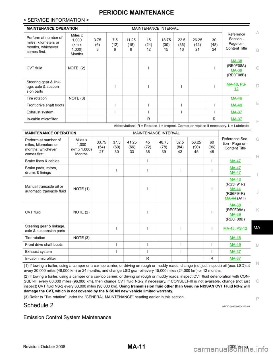
Abbreviations: R = Replace. I = Inspect. Corr
ect or replace if necessary. L = Lubricate.
(1) If towing a trailer, using a camper or a car-top carrier, or driving on rough or muddy roads, change (not just inspect) oil (exc. LSD) at
every 30,000 miles (48,000 km) or 24 months, and change LSD gear oil every 15,000 miles (24,000 km) or 12 months.
(2) If towing a trailer, using a camper or a car-top carrier, or driving on rough or muddy roads, inspect CVT fluid deteriorati on with CON-
SULT-III every 60,000 miles (96,000 km), then change CVT fluid NS-2 if necessary. If CONSULT-III is not available, change (not just
inspect) CVT fluid NS-2 every 60,000 miles (96,000 km). Using transmission fluid other than Genuine NISSAN CVT Fluid NS-2 will
damage the CVT, which is not covered by the NISSAN new vehicle limited warranty.
(3) Refer to “Tire rotation” under the “GENERAL MAINTENANCE” heading earlier in this section.
Schedule 2 INFOID:0000000004305186
Emission Control System Maintenance CVT fluid NOTE (2) I I
MA-38
(RE0F08A) MA-39
(RE0F08B)
Steering gear & link-
age, axle & suspen-
sion parts I I I I
MA-48 ,
PS- 12
Tire rotation NOTE (3)
MA-46Front drive shaft boots I I I I
MA-49Exhaust system I I I I
MA-37In-cabin microfilter R R
MA-37Brake pads, rotors,
drums & linings I I I I MA-47 MA-47
Manual transaxle oil or
automatic transaxle fluid NOTE (1) I I MA-43
(RS5F91R) MA-44
(RS6F94R)
MA-44 (A/T)
CVT fluid NOTE (2) I I MA-38
(RE0F08A)
MA-39
(RE0F08B)
Steering gear & linkage,
axle & suspension parts I I I I
MA-48 ,
PS-12 Tire rotation NOTE (3)
MA-46Front drive shaft boots I I I I
MA-49Exhaust system I I I I
MA-37In-cabin microfilter R R
MA-37
Page 3780 of 4331
MA
N
O P
CHASSIS AND BODY MAINTENANCE
IN-CABIN MICROFILTER
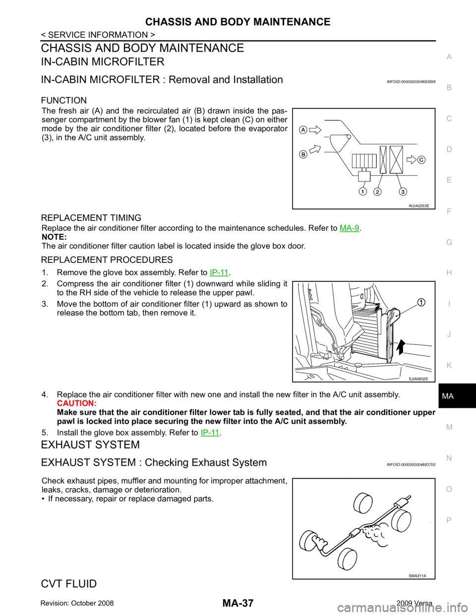
IN-CABIN MICROFILTER : Removal and Installation INFOID:0000000004683699
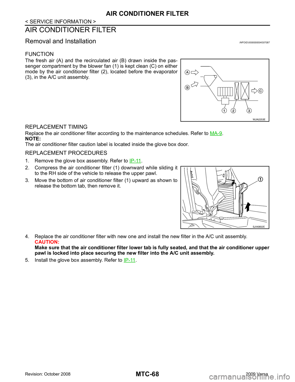
FUNCTION The fresh air (A) and the recirculated air (B) drawn inside the pas-
senger compartment by the blower fan (1) is kept clean (C) on either
mode by the air conditioner filter (2), located before the evaporator
(3), in the A/C unit assembly.
REPLACEMENT TIMING Replace the air conditioner filter according to the maintenance schedules. Refer to MA-9 .
NOTE:
The air conditioner filter caution label is located inside the glove box door.
REPLACEMENT PROCEDURES 1. Remove the glove box assembly. Refer to IP-11 .
2. Compress the air conditioner filter (1) downward while sliding it to the RH side of the vehicle to release the upper pawl.
3. Move the bottom of air conditioner filter (1) upward as shown to
release the bottom tab, then remove it.
4. Replace the air conditioner filter with new one and in stall the new filter in the A/C unit assembly.
CAUTION:
Make sure that the air cond itioner filter lower tab is fully seated , and that the air conditioner upper
pawl is locked into place securing the new filter into the A/C unit assembly.
5. Install the glove box assembly. Refer to IP-11 .
EXHAUST SYSTEM
EXHAUST SYSTEM : Chec king Exhaust System INFOID:0000000004683700
Check exhaust pipes, muffler and mounting for improper attachment,
leaks, cracks, damage or deterioration.
• If necessary, repair or replace damaged parts.
CVT FLUID SMA211A
Page 3789 of 4331
MA-46< SERVICE INFORMATION >
CHASSIS AND BODY MAINTENANCE
WHEELS : Rotation INFOID:0000000004683838
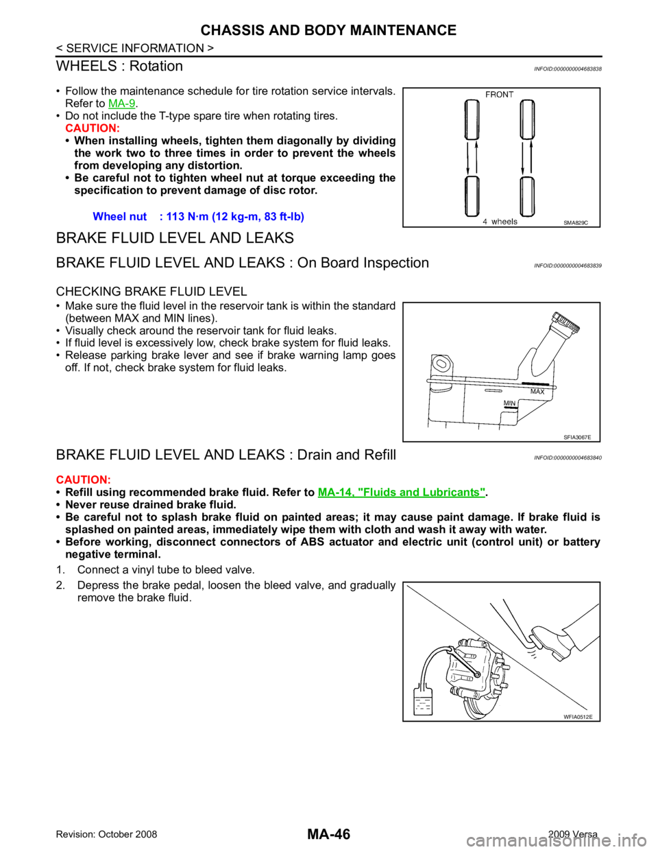
• Follow the maintenance schedule for tire rotation service intervals. Refer to MA-9 .
• Do not include the T-type spare tire when rotating tires.
CAUTION:
• When installing wheels, tighten them diagonally by dividing
the work two to three times in order to prevent the wheels
from developing any distortion.
• Be careful not to tighten wheel nut at torque exceeding the specification to prevent damage of disc rotor.
BRAKE FLUID LEVEL AND LEAKS
BRAKE FLUID LEVEL AND LEAK S : On Board Inspection INFOID:0000000004683839
CHECKING BRAKE FLUID LEVEL
• Make sure the fluid level in the reservoir tank is within the standard (between MAX and MIN lines).
• Visually check around the reservoir tank for fluid leaks.
• If fluid level is excessively low, check brake system for fluid leaks.
• Release parking brake lever and see if brake warning lamp goes off. If not, check brake system for fluid leaks.
BRAKE FLUID LEVEL AND LE AKS : Drain and Refill INFOID:0000000004683840
CAUTION:
• Refill using recommended brake fluid. Refer to MA-14, " Fluids and Lubricants " .
• Never reuse drained brake fluid.
• Be careful not to splash brake fluid on painted areas; it may cause paint damage. If brake fluid is
splashed on painted areas, immediately wipe th em with cloth and wash it away with water.
• Before working, disconnect connectors of ABS actua tor and electric unit (control unit) or battery
negative terminal.
1. Connect a vinyl tube to bleed valve.
2. Depress the brake pedal, loosen the bleed valve, and gradually remove the brake fluid.Wheel nut : 113 N·m (12 kg-m, 83 ft-lb) SMA829C
SFIA3067E
WFIA0512E
Page 3953 of 4331
MTC-68< SERVICE INFORMATION >
AIR CONDITIONER FILTER
AIR CONDITIONER FILTER
Removal and Installation INFOID:0000000004307087
FUNCTION
The fresh air (A) and the recirculated air (B) drawn inside the pas-
senger compartment by the blower fan (1) is kept clean (C) on either
mode by the air conditioner filter (2), located before the evaporator
(3), in the A/C unit assembly.
REPLACEMENT TIMING
Replace the air conditioner filter accord ing to the maintenance schedules. Refer to MA-9 .
NOTE:
The air conditioner filter caution label is located inside the glove box door.
REPLACEMENT PROCEDURES
1. Remove the glove box assembly. Refer to IP-11 .
2. Compress the air conditioner filter (1) downward while sliding it to the RH side of the vehicle to release the upper pawl.
3. Move the bottom of air conditioner filter (1) upward as shown to release the bottom tab, then remove it.
4. Replace the air conditioner filter with new one and install the new filter in the A/C unit assembly. CAUTION:
Make sure that the air conditioner filter lower tab is fully seated, and that the air conditioner upper
pawl is locked into place securing the ne w filter into the A/C unit assembly.
5. Install the glove box assembly. Refer to IP-11 . WJIA2253E
SJIA0652E
Page 4117 of 4331
.
3. Wheel bearing axial end play. Refer to RAX-5, " On-Vehicle Inspection and Service " .
4. Shock absorber operation.
5. Each mounting part of suspension for looseness and deformation.
6. Rear suspension beam for cracks, deformation, and other damage.
7. Vehicle height (posture).
GENERAL INFORMATION AND RECOMMENDATIONS
1. A Four-Wheel Thrust Alignment should be performed. • This type of alignment is recommended for any NISSAN vehicle.
• The four-wheel “thrust” process helps ensure that the vehicle is properly aligned and the steering wheel
is centered.
• The alignment machine itself should be ca pable of accepting any NISSAN vehicle.
• The alignment machine should be checked to ensure that it is level.
2. Make sure the alignment machine is properly calibrated. • Your alignment machine should be regularly calibrated in order to give correct information.
• Check with the manufacturer of your specific al ignment machine for their recommended Service/Cali-
bration Schedule.
THE ALIGNMENT PROCESS
IMPORTANT: Use only the alignment specifications listed in this Service Manual. Refer to RSU-13, " Wheel
Alignment (Unladen*) " .
1. When displaying the alignment settings, many alignm ent machines use “indicators”: (Green/red, plus or
minus, Go/No Go). Do NOT use these indicators.
• The alignment specifications programmed into your alignment machine that operate these indicators
may not be correct.
• This may result in an ERROR.
2. Some newer alignment machines are equipped with an optional “Rolling Compensation” method to “com- pensate” the sensors (alignment targets or head units). Do NOT use this “Rolling Compensation”
method.
• Use the “Jacking Compensation” method. After inst alling the alignment targets or head units, raise the
vehicle and rotate the wheels 1/2 turn both ways.
• See Instructions in the alignment machine you are using for more information.
CAMBER INSPECTION
Page 4272 of 4331
ROAD WHEEL TIRE ASSEMBLY
WT-7
< SERVICE INFORMATION >
C
D
F
G H
I
J
K L
M A
B WT
N
O P
ROAD WHEEL TIRE ASSEMBLY
Balancing Wheels INFOID:0000000004307317
Adjust wheel balance using road wheel center.
CAUTION:
• Be careful not to scratch th e road wheel during removal.
• Use clip-on type wheel balance weights only.
Wheel balance (Maximum allowable unbalance):
Rotation INFOID:0000000004307318
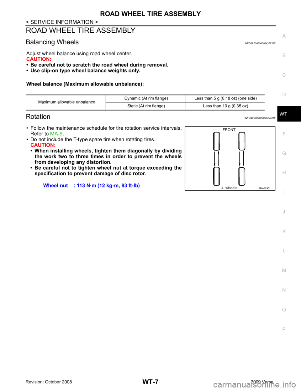
• Follow the maintenance schedule for tire rotation service intervals. Refer to MA-9 .
• Do not include the T-type spare tire when rotating tires. CAUTION:
• When installing wheels, tighte n them diagonally by dividing
the work two to three times in order to prevent the wheels
from developing any distortion.
• Be careful not to tighten wh eel nut at torque exceeding the
specification to prevent damage of disc rotor.
Maximum allowable unbalance
Dynamic (At rim flange) Less than 5 g (0.18 oz) (one side)
Static (At rim flange) Less than 10 g (0.35 oz) Wheel nut : 113 N·m (12 kg-m, 83 ft-lb)
SMA829C