2009 NISSAN TIIDA engine control system
[x] Cancel search: engine control systemPage 89 of 4331
AT-84< SERVICE INFORMATION >
TROUBLE DIAGNOSIS
Description
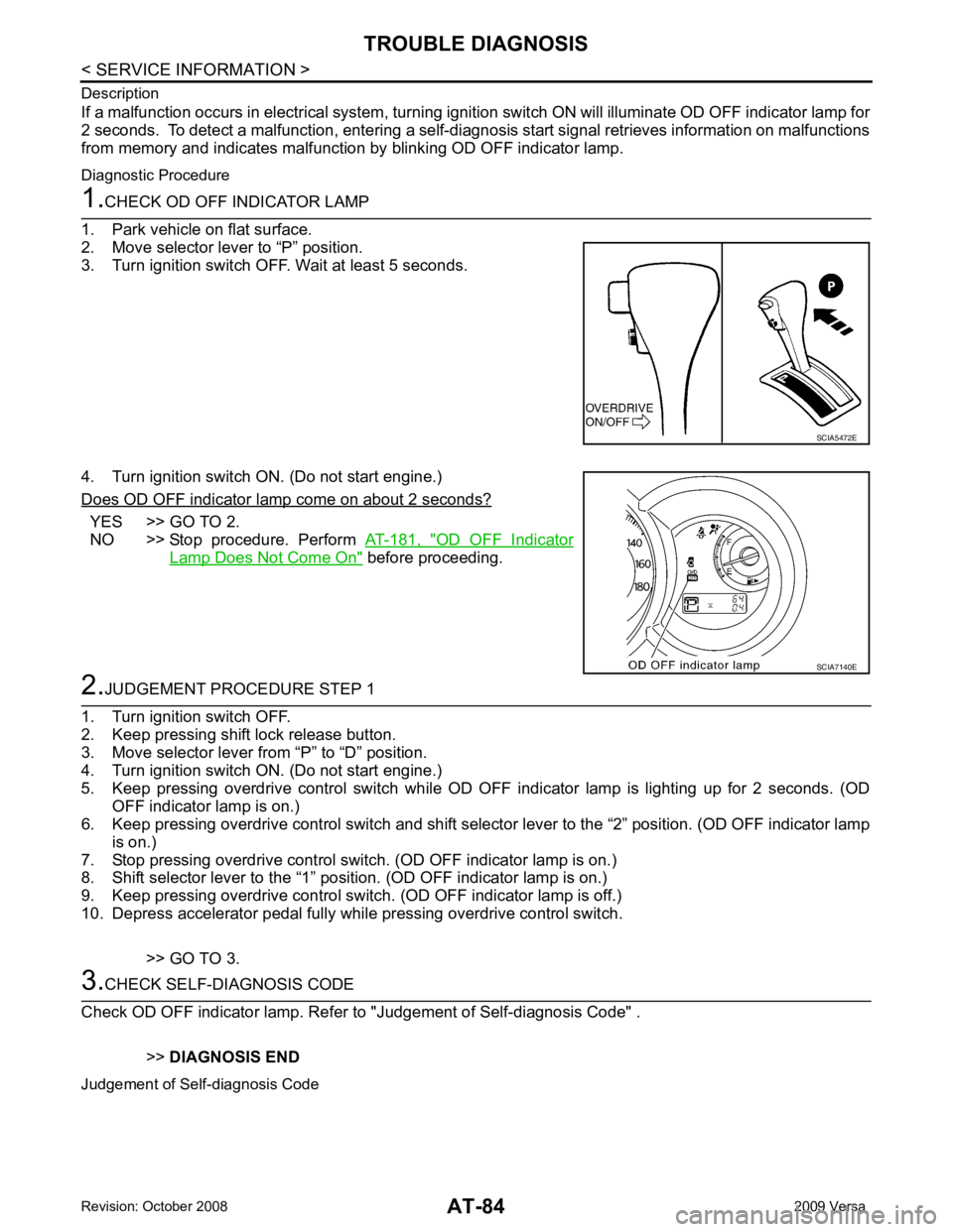
If a malfunction occurs in electrical system, turning igni tion switch ON will illuminate OD OFF indicator lamp for
2 seconds. To detect a malfunction, entering a self-diagnosis start signal retrieves information on malfunctions
from memory and indicates malfunction by blinking OD OFF indicator lamp.
Diagnostic Procedure 1.
CHECK OD OFF INDICATOR LAMP
1. Park vehicle on flat surface.
2. Move selector lever to “P” position.
3. Turn ignition switch OFF. Wait at least 5 seconds.
4. Turn ignition switch ON. (Do not start engine.)
Does OD OFF indicator lamp come on about 2 seconds? YES >> GO TO 2.
NO >> Stop procedure. Perform AT-181, " OD OFF Indicator
Lamp Does Not Come On " before proceeding.
2.
JUDGEMENT PROCEDURE STEP 1
1. Turn ignition switch OFF.
2. Keep pressing shift lock release button.
3. Move selector lever from “P” to “D” position.
4. Turn ignition switch ON. (Do not start engine.)
5. Keep pressing overdrive control switch while OD OF F indicator lamp is lighting up for 2 seconds. (OD
OFF indicator lamp is on.)
6. Keep pressing overdrive control switch and shift select or lever to the “2” position. (OD OFF indicator lamp
is on.)
7. Stop pressing overdrive control switch. (OD OFF indicator lamp is on.)
8. Shift selector lever to the “1” position. (OD OFF indicator lamp is on.)
9. Keep pressing overdrive control switch. (OD OFF indicator lamp is off.)
10. Depress accelerator pedal fully while pressing overdrive control switch.
>> GO TO 3. 3.
CHECK SELF-DIAGNOSIS CODE
Check OD OFF indicator lamp. Refer to "Judgement of Self-diagnosis Code" .
>>DIAGNOSIS END
Judgement of Self-diagnosis Code SCIA5472E
SCIA7140E
Page 202 of 4331
AT
N
O P
Check again. Refer to
AT-58, " Cruise Test - Part 1 " .
OK or NG OK >>
INSPECTION END
NG >> GO TO 3. TCM Terminal and Reference Value " .
2. If NG, recheck TCM pin terminals for dam age or loose connection with harness connector.
OK or NG OK >>
INSPECTION END
NG >> Repair or replace damaged parts.
Engine Speed Does Not Return to Idle (Light Braking D4→ D 3) INFOID:0000000004305486
SYMPTOM: Engine speed does not smoothly return to idle when A/T shifts from D4 to D 3 on “Cruise Test — Part
1”.
DIAGNOSTIC PROCEDURE CONSULT-III Functi
on (TRANSMISSION) " or
AT-83, " Diagnosis Pro-
cedure without CONSULT-III " .
Is any malfunction detected by self-diagnostic results? YES >> Check the malfuncti
oning system. Refer to AT-79, " CONSULT-III Functi
on (TRANSMISSION) " or
AT-83, " Diagnosis Procedure without CONSULT-III " .
NO >> GO TO 2. Description " (HR16DE),
EC-959, " Component
Description " (MR Type 1) or
EC-1481, " Component Description " (MR Type 2).
OK or NG OK >> GO TO 3.
NG >> Repair or replace accelerator pedal position sensor. Component " .
2. Check A/T fluid condition. Refer to AT-51, " Inspections Before Trouble Diagnosis " .
OK or NG OK >> GO TO 5.
NG >> GO TO 4. Control Valve Assembly and Accumulators " .
2. Check the following items:
- Overrun clutch control valve
- Overrun clutch reducing valve
- Overrun clutch solenoid valve
3. Disassemble A/T. Refer to AT-256, " Disassembly " .
4. Check the following items:
- Overrun clutch assembly. Refer to AT-306, " Forward and Overrun Clutches " .
OK or NG OK >> GO TO 6.
NG >> Repair or replace damaged parts. Control Valve Assembly and Accumulators " .
2. Check the following items:
Page 710 of 4331
BL
N
O P
- BCM
- Mechanical key
• NATS trouble diagnoses, system initialization and additional registration of other NATS mechanical key IDs
must be carried out using CONSULT-III hardware and CO NSULT-III NATS software. When NATS initializa-
tion has been completed, the ID of the inserted mechanical key can be displayed.
Regarding the procedures of NATS initialization and mec hanical key ID registration, refer to CONSULT-III
operation manual NATS.
SECURITY INDICATOR • Forewarns that the vehicle is equipped with NATS.
• Security indicator will not blink while the ignition knob is in ON or START state. NOTE:
Because security indicator is highly efficient, the battery is barely affected.
Condition of Secu rity Indicator
• When operating the ignition switch with Intelligent Key, se curity indicator lamp will turn off at once if ignition
switch is pressed and blinks when ignition switch is released.
• When operating the ignition switch with mechanical key security indicator will turn off at once if mechanical key is inserted into key cylinder and blinks when mechanical key is removed.
(Once the mechanical key is inserted into key cylinder, BCM will only perform the key ID verification with
mechanical key)
System Composition INFOID:0000000004305137
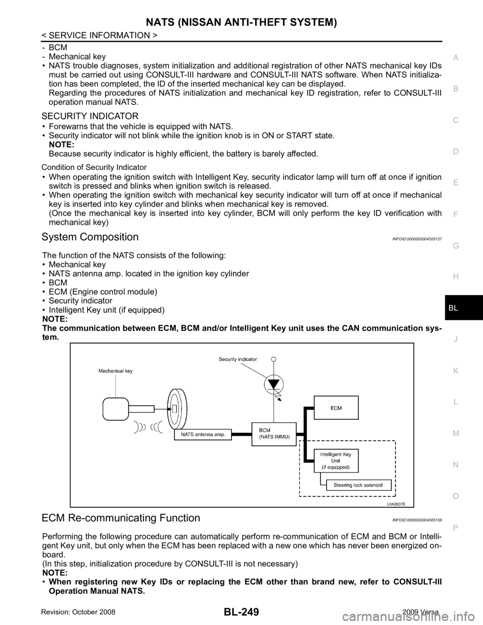
The function of the NATS consists of the following:
• Mechanical key
• NATS antenna amp. located in the ignition key cylinder
• BCM
• ECM (Engine control module)
• Security indicator
• Intelligent Key unit (if equipped)
NOTE:
The communication between ECM, BCM and/or Intelligent K ey unit uses the CAN communication sys-
tem.
ECM Re-communicating Function INFOID:0000000004305138
Performing the following procedure can automatically perform re-communication of ECM and BCM or Intelli-
gent Key unit, but only when the ECM has been replaced with a new one which has never been energized on-
board.
(In this step, initialization procedur e by CONSULT-III is not necessary)
NOTE:
• When registering new Key IDs or replacing the ECM other than brand new, refer to CONSULT-III
Operation Manual NATS.
Page 720 of 4331
BL
N
O P
This indication means that malfunction have been
detected in NATS and engine control system.
>> GO TO 8 U1000-U1010 " (MR type 1) or
EC-1015, " U0101-
U1001 " (MR type 2).
Without engine diagnostic codes present, refer to EC-577, " Trouble Diagnosis Introduction " (MR type 1) or
EC-1089, " Trouble Diagnosis Introduction " (MR type 2).
NOTE:
If only “NATS MALFUNCTION” is display ed, erase the self-diagnosis results.
>> GO TO 11
Page 843 of 4331
BRC
N
O P
Precaution for Brake Control
INFOID:0000000004307252
• During ABS operation, the brake pedal may vibrate lightly and a mechanical noise may be heard. This is normal.
• Just after starting the vehicle, the brake pedal may vibrate or motor operating noises may be heard from
engine compartment. This is normal due to the self check operation.
• Stopping distance may be longer than that of vehicles without ABS when vehicle drives on rough, gravel, or
snow-covered (fresh, deep snow) roads.
• When an error is indicated by ABS or another warning lamp, collect all necessary information from customer
(what symptoms are present under what conditions) and check for simple causes before starting diagnosis.
Besides electrical system inspection, check brake booster operation, brake fluid level, and fluid leaks.
• If incorrect tire sizes or types are installed on the vehicle or brake pads are not Genuine NISSAN parts, stop-
ping distance or steering stability may deteriorate.
• If there is a radio, antenna or related wiring near t he control module, ABS function may have a malfunction
or error.
• If aftermarket parts (car stereo, CD player, etc.) have been installed, check for incidents such as harness pinches, open circuits or improper wiring.
Precaution for CAN System INFOID:0000000004307253
• Do not apply voltage of 7.0V or higher to terminal to be measured.
• Maximum open terminal voltage of tester in use must be less than 7.0V.
• Before checking harnesses, turn ignition switch OFF and disconnect battery negative cable.
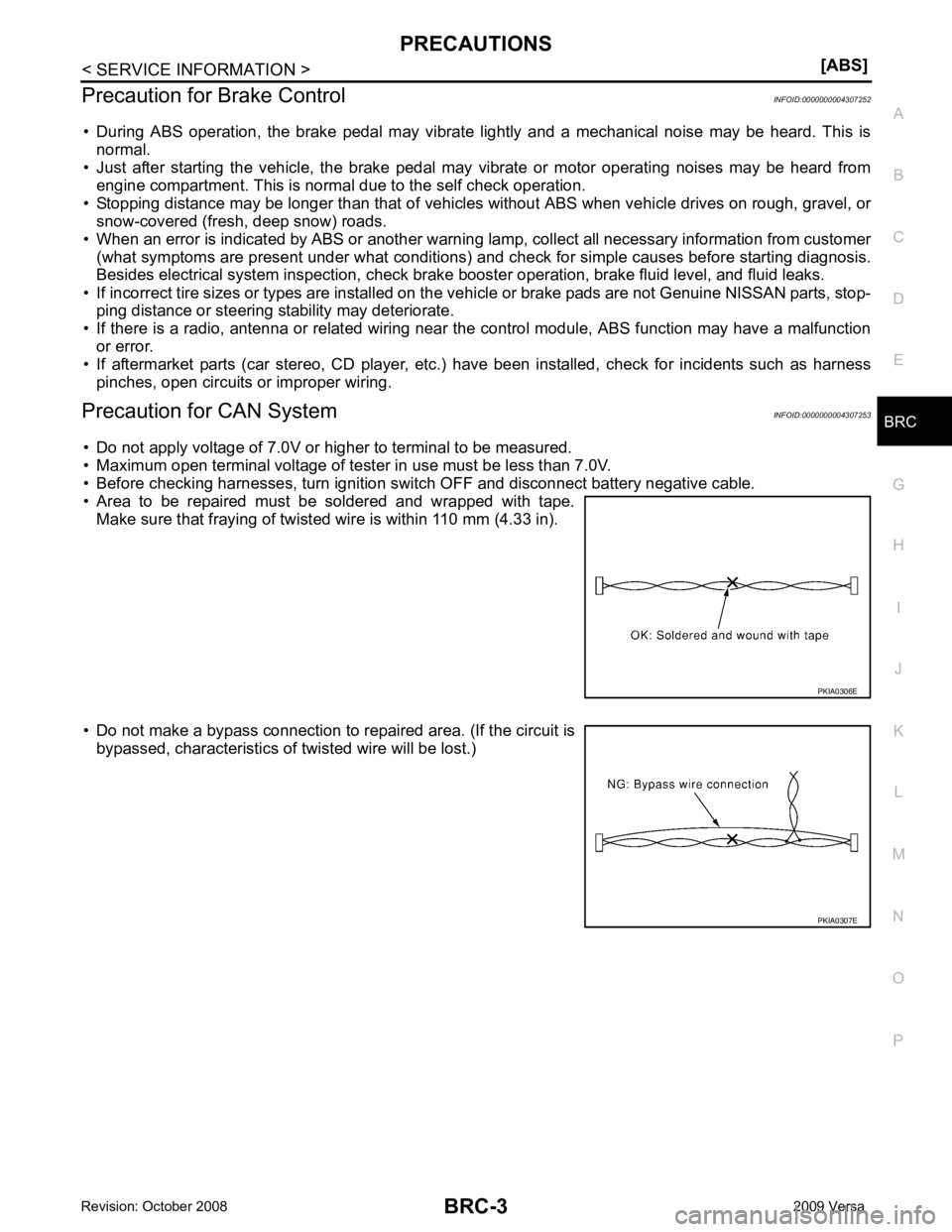
• Area to be repaired must be soldered and wrapped with tape. Make sure that fraying of twisted wire is within 110 mm (4.33 in).
• Do not make a bypass connection to repaired area. (If the circuit is bypassed, characteristics of twisted wire will be lost.)
Page 845 of 4331
BRC
N
O P
SYSTEM DESCRIPTION
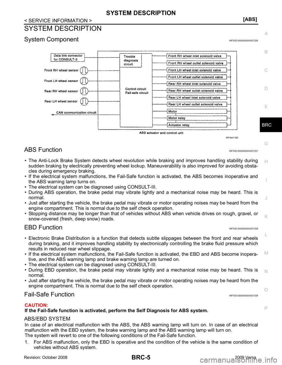
System Component INFOID:0000000004307256
ABS Function INFOID:0000000004307257
• The Anti-Lock Brake System detects wheel revolution while braking and improves handling stability during sudden braking by electrically preventing wheel lockup. Maneuverability is also improved for avoiding obsta-
cles during emergency braking.
• If the electrical system malfunctions, the Fail-Safe function is activated, the ABS becomes inoperative and
the ABS warning lamp turns on.
• The electrical system can be diagnosed using CONSULT-III.
• During ABS operation, the brake pedal may vibrate lightly and a mechanical noise may be heard. This is
normal.
• Just after starting the vehicle, the brake pedal may vibrate or motor operating noises may be heard from the
engine compartment. This is normal due to the self check operation.
• Stopping distance may be longer than that of vehicles without ABS when vehicle drives on rough, gravel, or
snow-covered (fresh, deep snow) roads.
EBD Function INFOID:0000000004307258
• Electronic Brake Distribution is a function that detec ts subtle slippages between the front and rear wheels
during braking, and it improves handling stability by elec tronically controlling the brake fluid pressure which
results in reduced rear wheel slippage.
• If the electrical system malfunctions, the Fail-Safe function is activated, the EBD and ABS become inopera-
tive, and the ABS warning lamp and brake warning lamp are turned on.
• The electrical system can be diagnosed using CONSULT-III.
• During EBD operation, the brake pedal may vibrate lightly and a mechanical noise may be heard. This is
normal.
• Just after starting the vehicle, the brake pedal may vibrate or motor operating noises may be heard from the
engine compartment. This is normal due to the self check operation.
Fail-Safe Function INFOID:0000000004307259
CAUTION:
If the Fail-Safe function is activated, perform the Self Diagnosis for ABS system.
ABS/EBD SYSTEM In case of an electrical malfunction with the ABS, the ABS warning lamp wi ll turn on. In case of an electrical
malfunction with the EBD system, the brake warni ng lamp and the ABS warning lamp will turn on.
The system will revert to one of the follo wing conditions of the Fail-Safe function.
1. For ABS malfunction, only the EBD is operative and t he condition of the vehicle is the same condition of
vehicles without ABS system.
Page 857 of 4331
BRC
N
O P
• If ABS actuator and electric unit (control unit) connec
tion is loose, tighten the piping to the specified
torque and recheck for leaks.
• If there is damage to the connection flare nut or A BS actuator and electric unit (control unit) threads,
replace the damaged part and recheck for leaks.
• When there is fluid leaking or seeping from a fluid connection, use a clean cloth to wipe off the fluid and recheck for leaks. If fluid is still seeping out, repl ace the damaged part. If the fluid is leaking at the ABS
actuator and electric unit (control unit), replace the ABS actuator and electric unit (control unit) assem-
bly.
CAUTION:
The ABS actuator and electric unit (control un it) cannot be disassembled and must be replaced
as an assembly.
3. Check the brake pads for excessive wear.
POWER SYSTEM TERMINAL LOOSENESS AND BATTERY INSPECTION Make sure the battery positive cable, negative cabl e and ground connection are not loose. In addition, make
sure the battery is sufficiently charged.
ABS WARNING LAMP INSPECTION 1. Make sure ABS warning lamp turns on for approximately 2 seconds when the ignition switch is turned ON. If it does not, check CAN communications. If ther e are no errors with the CAN communication system,
replace the combination meter. Refer to IP-12, " Removal and Installation " .
2. Make sure the lamp turns off approximately 2 seconds after the ignition switch is turned ON. If the lamp does not turn off, conduct self-diagnosis of ABS act uator and electric unit (control unit). If no malfunctions
are detected in self-diagnosis, replace combination meter. Refer to IP-12, " Removal and Installation " .
3. After conducting the self-diagnosis, be sure to erase the error memory. Refer to BRC-18, " CONSULT-III
Function (ABS) " .
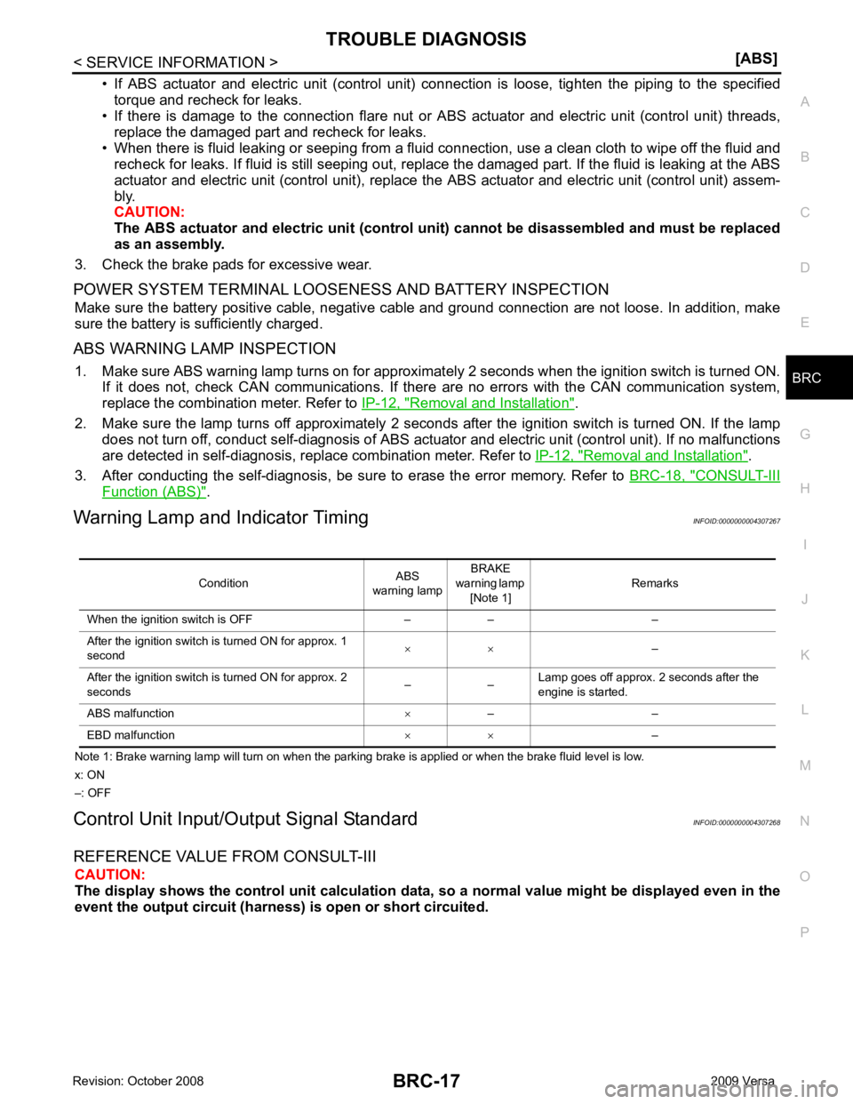
Warning Lamp and Indicator Timing INFOID:0000000004307267
Note 1: Brake warning lamp will turn on when the parking brake is applied or when the brake fluid level is low.
x: ON
–: OFF
Control Unit Input/Out put Signal Standard INFOID:0000000004307268
REFERENCE VALUE FROM CONSULT-III CAUTION:
The display shows the control unit calculation data, so a normal value might be displayed even in the
event the output circuit (harness) is open or short circuited.
Condition
ABS
warning lamp BRAKE
warning lamp [Note 1] Remarks
When the ignition switch is OFF – – –
After the ignition switch is turned ON for approx. 1
second × ×
–
After the ignition switch is turned ON for approx. 2
seconds – –Lamp goes off approx. 2 seconds after the
engine is started.
ABS malfunction ×– –
EBD malfunction × ×–
Page 858 of 4331
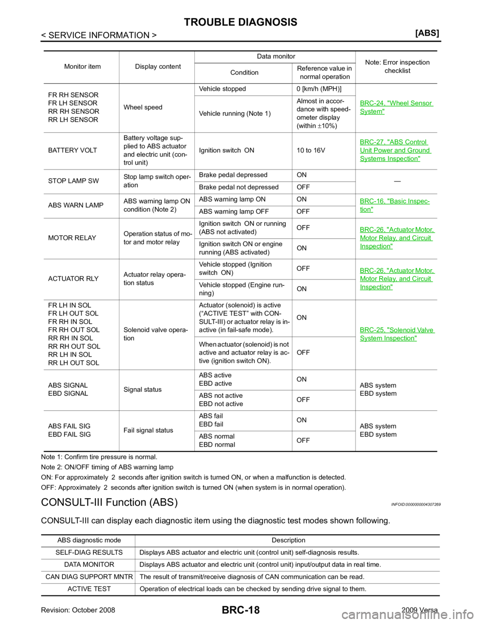
Wheel Sensor
System "
Vehicle running (Note 1)
Almost in accor-
dance with speed-
ometer display
(within ±10%)
BATTERY VOLT Battery voltage sup-
plied to ABS actuator
and electric unit (con-
trol unit) Ignition switch ON 10 to 16V
BRC-27, " ABS Control
Unit Power and Ground
Systems Inspection "
STOP LAMP SW
Stop lamp switch oper-
ation Brake pedal depressed ON
—
Brake pedal not depressed OFF
ABS WARN LAMP ABS warning lamp ON
condition (Note 2) ABS warning lamp ON ON
BRC-16, " Basic Inspec-
tion "
ABS warning lamp OFF OFF
MOTOR RELAY Operation status of mo-
tor and motor relay Ignition switch ON or running
(ABS not activated) OFF
BRC-26, " Actuator Motor,
Motor Relay, and Circuit
Inspection "Ignition switch ON or engine
running (ABS activated) ON
ACTUATOR RLY Actuator relay opera-
tion status Vehicle stopped (Ignition
switch ON) OFF
BRC-26, " Actuator Motor,
Motor Relay, and Circuit
Inspection "Vehicle stopped (Engine run-
ning) ON
FR LH IN SOL
FR LH OUT SOL
FR RH IN SOL
FR RH OUT SOL
RR RH IN SOL
RR RH OUT SOL
RR LH IN SOL
RR LH OUT SOL Solenoid valve opera-
tion Actuator (solenoid) is active
(“ACTIVE TEST” with CON-
SULT-III) or actuator relay is in-
active (in fail-safe mode). ON
BRC-25, " Solenoid Valve
System Inspection "
When actuator (solenoid) is not
active and actuator relay is ac-
tive (ignition switch ON). OFF
ABS SIGNAL
EBD SIGNAL Signal statusABS active
EBD active ON
ABS system
EBD system
ABS not active
EBD not active OFF
ABS FAIL SIG
EBD FAIL SIG Fail signal statusABS fail
EBD fail ON
ABS system
EBD system
ABS normal
EBD normal OFFABS diagnostic mo
de Description
SELF-DIAG RESULTS Displays ABS actuator and electric unit (control unit) self-diagnosis results.
DATA MONITOR Displays ABS actuator and electric unit (control unit) input/output data in real time.
CAN DIAG SUPPORT MNTR The result of transmit/receive diagnosis of CAN communication can be read. ACTIVE TEST Operation of electrical loads can be checked by sending drive signal to them.