Page 615 of 4331
OK >> GO TO 5
NG >> Repair or replace harness. OK >> CVT or A/T device (park position switch) circuit is OK.
NG >> Replace Intelligent Key unit. Refer to BL-158, " Removal
and Installation of Intelligent Key Unit " .
"P-SHIFT" Warning Lamp (With CVT or A/T) Check INFOID:0000000004305066OK >> Inspection End.
NG >> Check combination meter. Refer to DI-3 .
10 – 8 : Continuity should exist.
10 – Ground : Continuity should not exist. WIIA1262E
Page 616 of 4331
BL
N
O P
"LOCK" Warning Lamp (With M/T) Check
INFOID:0000000004305067OK >> Inspection End.
NG >> Check combination meter. Refer to DI-3 .
"KEY" Warning Lamp (RED) Check INFOID:0000000004305068OK >> Inspection End.
NG >> Check combination meter. Refer to DI-3 .
"KEY" Warning Lamp (GREEN) Check INFOID:0000000004305069 WIIA1264E
Page 618 of 4331

INTELLIGENT KEY SYSTEM
BL-157
< SERVICE INFORMATION >
C
D E
F
G H
J
K L
M A
B BL
N
O P
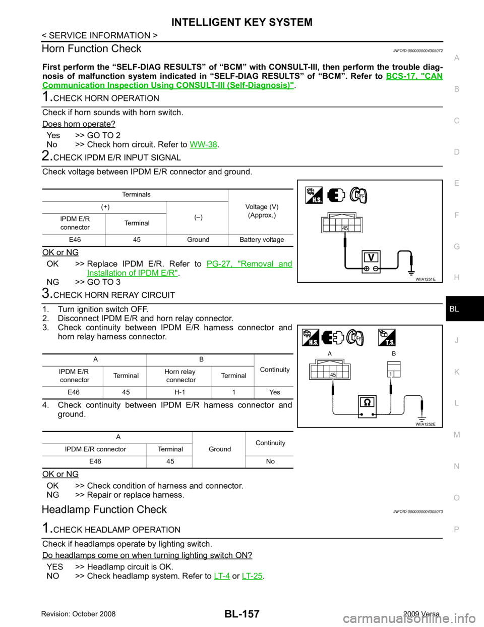
Horn Function Check
INFOID:0000000004305072
First perform the “SELF-DIAG RESULTS” of “BCM” with CONSULT-III, then perform the trouble diag-
nosis of malfunction system indicated in “ SELF-DIAG RESULTS” of “BCM”. Refer to BCS-17, " CAN
Communication Inspection Using CONSULT-III (Self-Diagnosis) " .
1.
CHECK HORN OPERATION
Check if horn sounds with horn switch.
Does horn operate? Yes >> GO TO 2
No >> Check horn circuit. Refer to WW-38 .
2.
CHECK IPDM E/R INPUT SIGNAL
Check voltage between IPDM E/R connector and ground.
OK or NG OK >> Replace IPDM E/R. Refer to
PG-27, " Removal and
Installation of IPDM E/R " .
NG >> GO TO 3 3.
CHECK HORN RERAY CIRCUIT
1. Turn ignition switch OFF.
2. Disconnect IPDM E/R and horn relay connector.
3. Check continuity between IPDM E/R harness connector and horn relay harness connector.
4. Check continuity between IPDM E/R harness connector and ground.
OK or NG OK >> Check condition of harness and connector.
NG >> Repair or replace harness.
Headlamp Function Check INFOID:00000000043050731.
CHECK HEADLAMP OPERATION
Check if headlamps operate by lighting switch.
Do headlamps come on when turning lighting switch ON? YES >> Headlamp circuit is OK.
NO >> Check headlamp system. Refer to LT-4 or
LT-25 .
Terminals
Voltage (V)(Approx.)
(+)
(–)
IPDM E/R
connector Terminal
E46 45 Ground Ba ttery voltage WIIA1251E
A B
Continuity
IPDM E/R
connector Terminal
Horn relay
connector Terminal
E46 45 H-1 1 Yes
A GroundContinuity
IPDM E/R connector Terminal
E46 45 No WIIA1252E
Page 620 of 4331
BL
N
O P
2. Disconnect Intelligent Key unit connector, remove screw and
Intelligent Key unit.
INSTALLATION Installation is in the reverse order of removal.
Page 627 of 4331
Removal and Installation " .
2. Fully close front door window.
3. Remove the front door sealing screen. NOTE:
If sealing screen is reused, cut butyl tape in a way that leaves it on the sealing screen.
4. Remove front door rear glass run channel. Refer to GW-44, " Removal and Installation " .
5. Remove the cables from the holder.
6. Remove inside handle bolt, and slide the handle toward the rear of the vehicle.
7. Disengage the handle from the door panel, and remove the inside handle. 1. Front door 2. Inside handle 3. Inside handle cable
4. Door lock assembly 5. Outside handle cable 6. TORX bolt (T30)
7. Key cylinder connecting rod 8. Grommet 9. TORX bolt (T30)
10. Rear gasket 11. Door key cylinder assembly (Driver's side)
Outside handle escutcheon
(passenger's side) 12. Outside handle
13. Front gasket 14. Lock knob cable 15. Holder
16. Outside handle bracket PIIB6524E
Page 628 of 4331
BL
N
O P
8. Disconnect the inside handle cable and lock knob cable from the
inside handle.
CAUTION:
During removal and installation , work so as not to bend the
ends of the lock knob cable and inside handle cable.
9. Remove the door side grommet, and the door key cylinder assembly (escutcheon) bolt.
10. Remove the key cylinder connecting rod (key cylinder side).
11. If equipped, disconnect the door antenna, the door request switch connector and remove the harness clamp. (Vehicle with
intelligent key systems only).
12. Remove the door cylinder assembly while pulling the outside handle forward.
13. Pull the outside door handle forward and then slide it toward the rear of the vehicle to remove.
14. Remove the front and rear gaskets. PIIB5808E
PIIB5809E
PIIB6526E
Page 634 of 4331
BL
N
O P
Ground is supplied
• to back door lock assembly (actuator) terminal 2
• through body grounds B117, B132 and D402.
Then BCM operates back door lock assembly (actuator).
Wiring Diagram - B/DOOR - INFOID:0000000004305085
WITHOUT INTELLIGENT KEY SYSTEM B
Page 636 of 4331

BACK DOOR LOCK
BL-175
< SERVICE INFORMATION >
C
D E
F
G H
J
K L
M A
B BL
N
O P
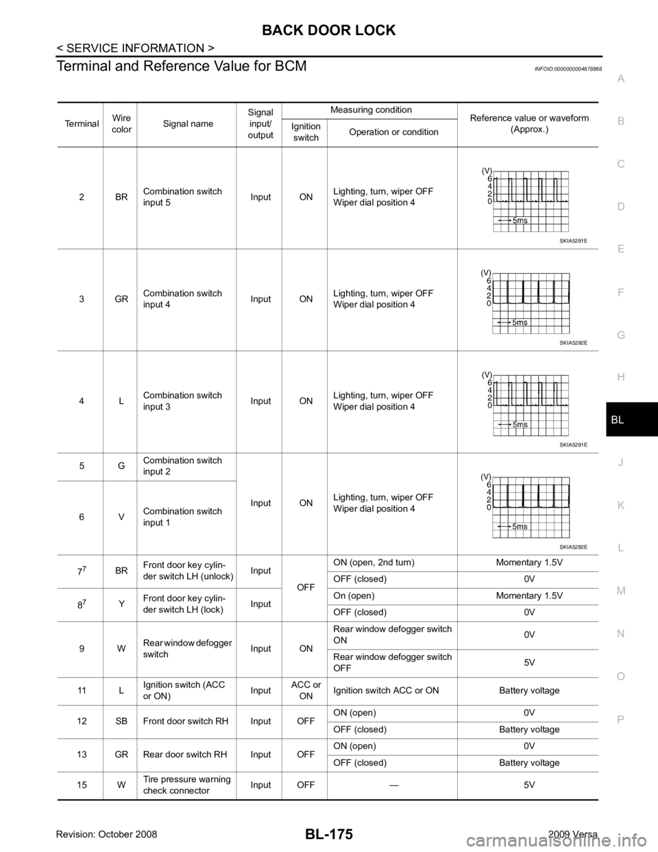
Terminal and Reference Value for BCM
INFOID:0000000004678868
Terminal Wire
color Signal name Signal
input/
output Measuring condition
Reference value or waveform
(Approx.)
Ignition
switch Operation or condition
2 BR Combination switch
input 5 Input ONLighting, turn, wiper OFF
Wiper dial position 4
3 GR Combination switch
input 4 Input ONLighting, turn, wiper OFF
Wiper dial position 4
4 L Combination switch
input 3 Input ONLighting, turn, wiper OFF
Wiper dial position 4
5 G Combination switch
input 2
Input ONLighting, turn, wiper OFF
Wiper dial position 4
6 V Combination switch
input 1
7 7
BRFront door key cylin-
der switch LH (unlock) Input
OFFON (open, 2nd turn) Momentary 1.5V
OFF (closed) 0V
8 7
YFront door key cylin-
der switch LH (lock) InputOn (open) Momentary 1.5V
OFF (closed) 0V
9 W Rear window defogger
switch Input ONRear window defogger switch
ON 0V
Rear window defogger switch
OFF 5V
11 L Ignition switch (ACC
or ON) InputACC or
ON Ignition switch ACC or ON Battery voltage
12 SB Front door switch RH Input OFF ON (open) 0V
OFF (closed) Battery voltage
13 GR Rear door switch RH Input OFF ON (open) 0V
OFF (closed) Battery voltage
15 W Tire pressure warning
check connector Input OFF — 5V SKIA5291E
SKIA5292E
SKIA5291E
SKIA5292E