2009 NISSAN TIIDA Camshaft position sensor
[x] Cancel search: Camshaft position sensorPage 2869 of 4331
![NISSAN TIIDA 2009 Service Repair Manual FUEL PUMP
EC-1513
< SERVICE INFOMATION >
[MR TYPE 2] C
D E
F
G H
I
J
K L
M A EC
NP
O
FUEL PUMP
Description INFOID:0000000004500415
SYSTEM DESCRIPTION
*: ECM determines the start signal status by the s](/manual-img/5/57398/w960_57398-2868.png "NISSAN TIIDA 2009 Service Repair Manual FUEL PUMP
EC-1513
< SERVICE INFOMATION >
[MR TYPE 2] C
D E
F
G H
I
J
K L
M A EC
NP
O
FUEL PUMP
Description INFOID:0000000004500415
SYSTEM DESCRIPTION
*: ECM determines the start signal status by the s")
FUEL PUMP
EC-1513
< SERVICE INFOMATION >
[MR TYPE 2] C
D E
F
G H
I
J
K L
M A EC
NP
O
FUEL PUMP
Description INFOID:0000000004500415
SYSTEM DESCRIPTION
*: ECM determines the start signal status by the signals of engine speed and battery voltage.
The ECM activates the fuel pump for several seconds after the ignition switch is turned ON to improve engine
start ability. If the ECM receives a engine speed signal from the crankshaft position sensor (POS) and cam-
shaft position sensor (PHASE), it knows that the engi ne is rotating, and causes the pump to operate. If the
engine speed signal is not received when the ignition s witch is ON, the engine stalls. The ECM stops pump
operation and prevents battery discharging, thereby improving safety. The ECM does not directly drive the fuel
pump. It controls the ON/OFF fuel pump rela y, which in turn controls the fuel pump.
COMPONENT DESCRIPTION A turbine type design fuel pump is used in the fuel tank.
• Fuel level sensor unit and fuel pump (1)
• Fuel pressure regulator (2)
• Fuel level sensor (3)
• Fuel tank temperature sensor (4)
CONSULT-III Reference Val ue in Data Monitor Mode INFOID:0000000004500416
Specification data are reference values. Sensor Input Signal to ECM ECM Function Actuator
Crankshaft position sensor (POS)
Camshaft position sensor (PHASE) Engine speed*
Fuel pump control Fuel pump relay
Battery Battery voltage* Condition Fuel pump operation
Ignition switch is turned to ON Operates for 1 second
Engine running and cranking Operates
Engine: Stopped Stops in 1.5 seconds
Except as shown above Stops BBIA0704E
MONITOR ITEM CONDITION SPECIFICATION
FUEL PUMP RLY • For 1 second after turning ignition switch ON
• Engine running or cranking ON
• Except above conditions OFF
Page 2891 of 4331
EC
NP
O
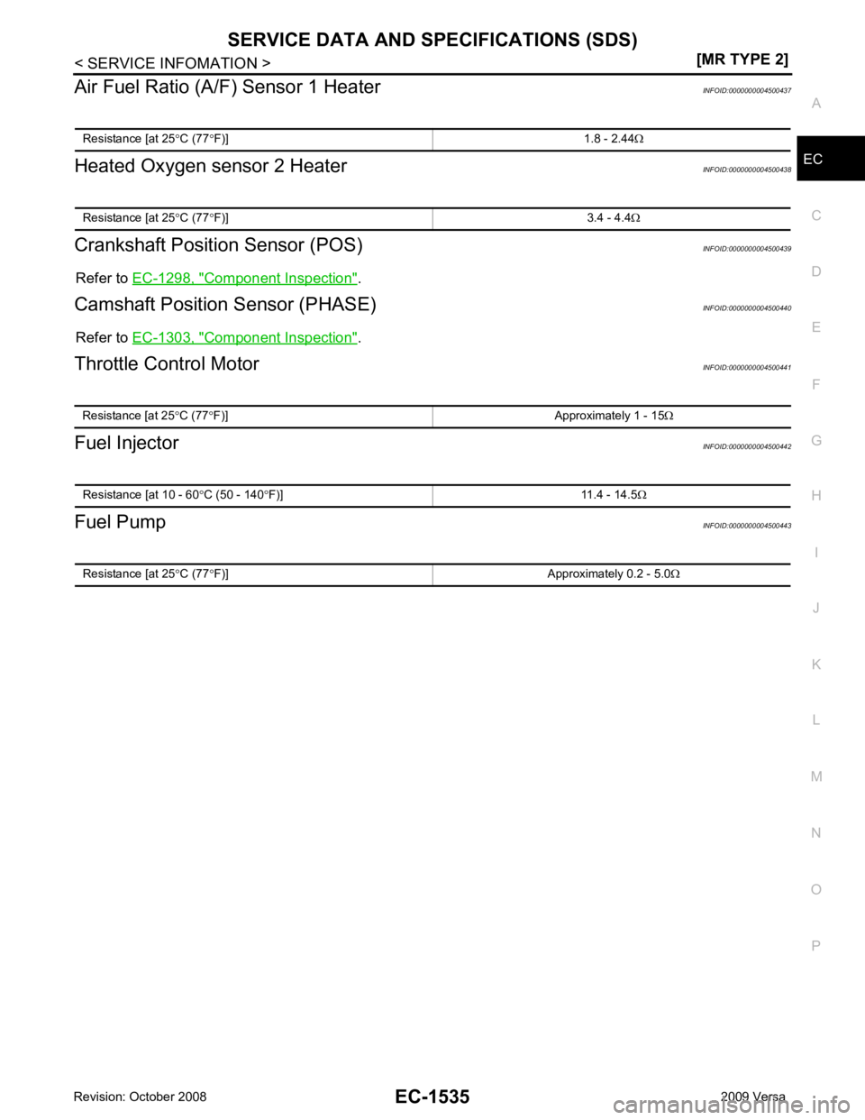
Air Fuel Ratio (A/F) Sensor 1 Heater
INFOID:0000000004500437
Heated Oxygen sensor 2 Heater INFOID:0000000004500438
Crankshaft Position Sensor (POS) INFOID:0000000004500439
Refer to EC-1298, " Component Inspection " .
Camshaft Position Sensor (PHASE) INFOID:0000000004500440
Refer to EC-1303, " Component Inspection " .
Throttle Control Motor INFOID:0000000004500441
Fuel Injector INFOID:0000000004500442
Fuel Pump INFOID:0000000004500443
Resistance [at 25
°C (77 °F)] 1.8 - 2.44 Ω
Page 3005 of 4331
Rotation " .
2. Remove front fender protector (RH). Refer to EI-24, " Removal and Installation " .
3. Drain engine oil. Refer to LU-8, " Draining " .
CAUTION:
Be sure to perform this step when engine is cold.
4. Remove the following parts. • Intake manifold: Refer to EM-28, " Exploded View " .
• Drive belt: Refer to EM-15, " Removal and Installation " .
• Water pump pulley: Refer to CO-20, " Exploded View " .
• Ground cable (RH)
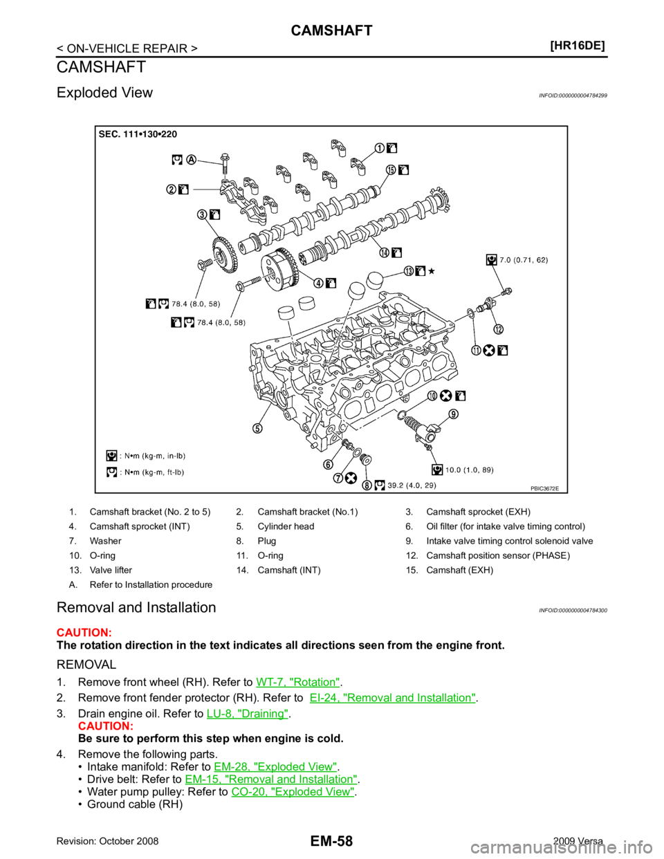
1. Camshaft bracket (No. 2 to 5) 2. Camshaft bracket (No.1) 3. Camshaft sprocket (EXH)
4. Camshaft sprocket (INT) 5. Cylinder head 6. Oil filter (for intake valve timing control)
7. Washer 8. Plug 9. Intake valve timing control solenoid valve
10. O-ring 11. O-ring 12. Camshaf t position sensor (PHASE)
13. Valve lifter 14. Camshaft (INT) 15. Camshaft (EXH)
A. Refer to Installation procedure
Page 3007 of 4331
![NISSAN TIIDA 2009 Service Repair Manual EM-60< ON-VEHICLE REPAIR >
[HR16DE]
CAMSHAFT
a. Loosen bolts in the reverse of the order shown.
b. Cut liquid gasket by prying the position ( ) shown, and then remove the front cover.
10. Re](/manual-img/5/57398/w960_57398-3006.png "NISSAN TIIDA 2009 Service Repair Manual EM-60< ON-VEHICLE REPAIR >
[HR16DE]
CAMSHAFT
a. Loosen bolts in the reverse of the order shown.
b. Cut liquid gasket by prying the position ( ) shown, and then remove the front cover.
10. Re")
EM-60< ON-VEHICLE REPAIR >
[HR16DE]
CAMSHAFT
a. Loosen bolts in the reverse of the order shown.
b. Cut liquid gasket by prying the position ( ) shown, and then remove the front cover.
10. Remove camshaft position sensor (PHASE) from rear end of cylinder head. CAUTION:
Handle it carefully and avoid impacts.
11. Remove camshaft sprocket (EXH) (1). CAUTION:
• Hold the camshaft hexagonal part (A), and then secure the
camshaft.
• Never rotate crankshaft and camshaft separately, so as not to contact valve with pist on in the following steps.
12. Turn the camshaft sprocket (INT) to the most advanced position. CAUTION:
Installation and removal of the camshaft sprocket (INT) must be done in the most advanced posi-
tion for the following reasons. KBIA3429J
PBIC3712E
AWBIA0102ZZ
Page 3017 of 4331
![NISSAN TIIDA 2009 Service Repair Manual EM-70< ON-VEHICLE REPAIR >
[HR16DE]
CAMSHAFT
c. Tighten bolts in the numerical order shown.
d. After all bolts are tightened, retighten them to specified torque in numerical order as shown.
CAUTION:
B](/manual-img/5/57398/w960_57398-3016.png "NISSAN TIIDA 2009 Service Repair Manual EM-70< ON-VEHICLE REPAIR >
[HR16DE]
CAMSHAFT
c. Tighten bolts in the numerical order shown.
d. After all bolts are tightened, retighten them to specified torque in numerical order as shown.
CAUTION:
B")
EM-70< ON-VEHICLE REPAIR >
[HR16DE]
CAMSHAFT
c. Tighten bolts in the numerical order shown.
d. After all bolts are tightened, retighten them to specified torque in numerical order as shown.
CAUTION:
Be sure to wipe off any excessive liquid gasket leaking to
surface.
22. Insert crankshaft pulley by aligning with crankshaft key. • When inserting crankshaft pulley with a plastic hamme r, tap on its center portion (not circumference).
CAUTION:
Never damage front oil seal lip section.
23. Tighten crankshaft pulley bolt with the following procedure: • Secure crankshaft pulley with a suitable tool, and tighten crankshaft pulley bolt.
a. Apply new engine oil to thread and seat surfaces of crankshaft pulley bolt.
b. Tighten crankshaft pulley bolt.
c. Put a paint mark (B) on crankshaft pulley, mating with any one of six easy to recognize angle marks (A) on crankshaft bolt flange
(1).
d. Turn another 60 degrees clockwise (angle tightening). • Check the tightening angle with movement of one angle mark.
24. Make sure that crankshaft turns smoothly by rotating by hand clockwise.
25. Install the camshaft position sensor (PHASE) to the rear end of cylinder head.
• Tighten bolts with it seated completely.
26. Check and adjust valve clearance. Refer to EM-20, " Inspection and Adjustment " .
27. Installation of the remaining components is in the reverse order of removal.
Inspection INFOID:0000000004784301
INSPECTION AFTER REMOVAL
Oil Filter KBIA3429J
Crankshaft pulley bolt : 35.0 N·m (3.6 kg-m, 26 ft-lb)
PBIC3726E
Page 3118 of 4331
EM
NP
O
• Rocker cover; Refer to
EM-153 .
• Fuel tube and fuel injector assembly; Refer to EM-156 .
• Front cover, timing chain and related parts; Refer to EM-160 .
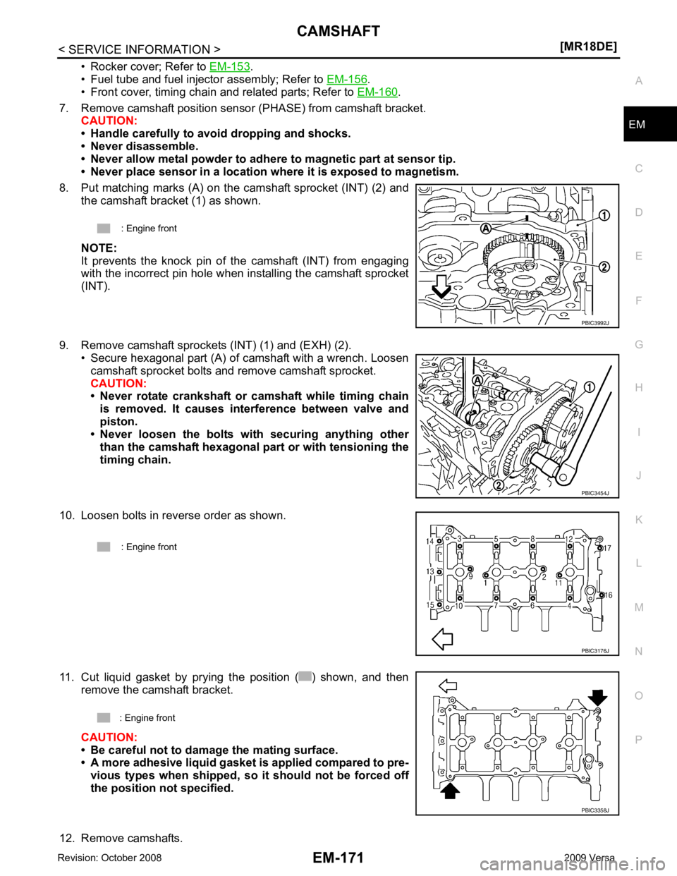
7. Remove camshaft position sensor (PHASE) from camshaft bracket. CAUTION:
• Handle carefully to avoid dropping and shocks.
• Never disassemble.
• Never allow metal powder to adhere to magnetic part at sensor tip.
• Never place sensor in a location wher e it is exposed to magnetism.
8. Put matching marks (A) on the camshaft sprocket (INT) (2) and the camshaft bracket (1) as shown.
NOTE:
It prevents the knock pin of the camshaft (INT) from engaging
with the incorrect pin hole when installing the camshaft sprocket
(INT).
9. Remove camshaft sprockets (INT) (1) and (EXH) (2). • Secure hexagonal part (A) of camshaft with a wrench. Loosen
camshaft sprocket bolts and remove camshaft sprocket.
CAUTION:
• Never rotate crankshaft or camshaft while timing chain
is removed. It causes interference between valve and
piston.
• Never loosen the bolts with securing anything other
than the camshaft hexagonal part or with tensioning the
timing chain.
10. Loosen bolts in reverse order as shown.
11. Cut liquid gasket by prying the position ( ) shown, and then remove the camshaft bracket.
CAUTION:
• Be careful not to damage the mating surface.
• A more adhesive liquid gasket is applied compared to pre-
vious types when shipped, so it should not be forced off
the position not specified.
12. Remove camshafts. : Engine front
PBIC3454J
Page 3300 of 4331

GI
N
O P
TERMINOLOGY
SAE J1930 Terminology List INFOID:0000000004307379
All emission related terms used in this publication in accordance with SAE J1930 are listed. Accordingly, new
terms, new acronyms/abbreviations and old terms are listed in the following chart.
NEW TERM NEW ACRONYM /
ABBREVIATION OLD TERM
Air cleaner ACL Air cleaner
Barometric pressure BARO ***
Barometric pressure se nsor-BCDD BAROS-BCDD BCDD
Camshaft position CMP ***
Camshaft position sensor CMPS Crank angle sensor
Canister *** Canister
Carburetor CARB Carburetor
Charge air cooler CAC Intercooler
Closed loop CL Closed loop
Closed throttle position switch CTP switch Idle switch
Clutch pedal position switch CPP switch Clutch switch
Continuous fuel injection system CFI system ***
Continuous trap oxidizer system CTOX system ***
Crankshaft position CKP ***
Crankshaft position sensor CKPS ***
Data link connector DLC ***
Data link connector fo r CONSULT-III DLC for CONSULT-III Di agnostic connector for CONSULT-III
Diagnostic test mode DTM Diagnostic mode
Diagnostic test mode selector DTM selector Diagnostic mode selector
Diagnostic test mode I DTM I Mode I
Diagnostic test mode II DTM II Mode II
Diagnostic trouble code DTC Malfunction code
Direct fuel injection system DFI system ***
Distributor ignition system DI system Ignition timing control
Early fuel evaporation-mixture heater EFE-mixture heater Mixture heater
Early fuel evaporation system EFE system Mixture heater control
Electrically erasable programmable read
only memory EEPROM ***
Electronic ignition system EI system Ignition timing control
Engine control EC ***
Engine control module ECM ECCS control unit
Engine coolant temperature ECT Engine temperature
Engine coolant temperature sensor ECTS Engine temperature sensor
Engine modification EM ***
Engine speed RPM Engine speed
Erasable programmable read only memory EPROM ***
Evaporative emission canister EVAP canister Canister
Evaporative emission system EVAP system Canister control solenoid valve
Exhaust gas recirculation valve EGR valve EGR valve
Page 4028 of 4331
PG
N
O P
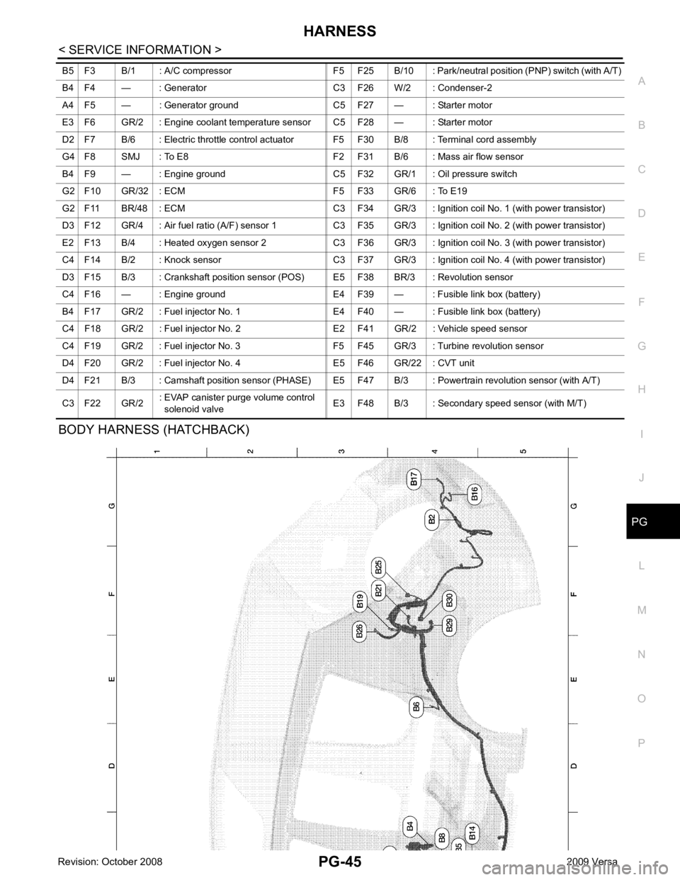
BODY HARNESS (HATCHBACK) B5 F3 B/1 : A/C compressor F5 F25 B/10 : Park/n
eutral position (PNP) switch (with A/T)
B4 F4 — : Generator C3 F26 W/2 : Condenser-2
A4 F5 — : Generator ground C5 F27 — : Starter motor
E3 F6 GR/2 : Engine coolant temperature sensor C5 F28 — : Starter motor
D2 F7 B/6 : Electric throttle control actuator F5 F30 B/8 : Terminal cord assembly
G4 F8 SMJ : To E8 F2 F31 B/6 : Mass air flow sensor
B4 F9 — : Engine ground C5 F32 GR/1 : Oil pressure switch
G2 F10 GR/32 : ECM F5 F33 GR/6 : To E19
G2 F11 BR/48 : ECM C3 F34 GR/3 : Ignition coil No. 1 (with power transistor)
D3 F12 GR/4 : Air fuel ratio (A/F) sensor 1 C3 F35 GR/3 : Ignition coil No. 2 (with power transistor)
E2 F13 B/4 : Heated oxygen sensor 2 C3 F36 GR/3 : Ignition coil No. 3 (with power transistor)
C4 F14 B/2 : Knock sensor C3 F37 GR/3 : Ignition coil No. 4 (with power transistor)
D3 F15 B/3 : Crankshaft position sensor (POS) E5 F38 BR/3 : Revolution sensor
C4 F16 — : Engine ground E4 F39 — : Fusible link box (battery)
B4 F17 GR/2 : Fuel injector No. 1 E4 F40 — : Fusible link box (battery)
C4 F18 GR/2 : Fuel injector No. 2 E2 F41 GR/2 : Vehicle speed sensor
C4 F19 GR/2 : Fuel injector No. 3 F5 F45 GR/3 : Turbine revolution sensor
D4 F20 GR/2 : Fuel injector No. 4 E5 F46 GR/22 : CVT unit
D4 F21 B/3 : Camshaft position sensor (PHASE) E5 F4 7 B/3 : Powertrain revolution sensor (with A/T)
C3 F22 GR/2 : EVAP canister purge volume control
solenoid valve E3 F48 B/3 : Secondary speed sensor (with M/T)