2009 NISSAN QASHQAI wheel torque
[x] Cancel search: wheel torquePage 188 of 297

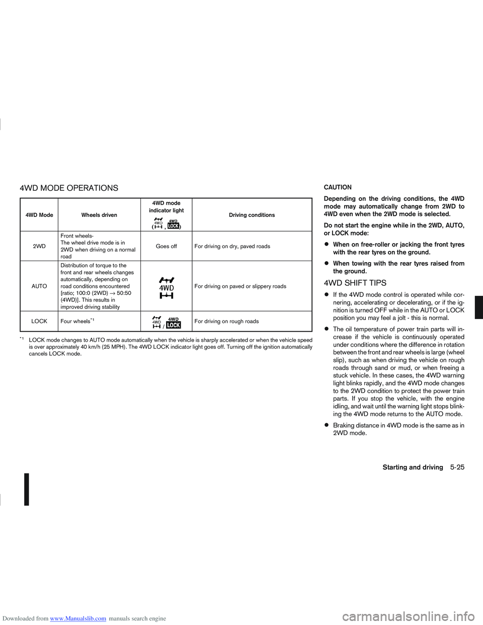
Downloaded from www.Manualslib.com manuals search engine 4WD MODE OPERATIONSCAUTION
Depending on the driving conditions, the 4WD
mode may automatically change from 2WD to
4WD even when the 2WD mode is selected.
Do not start the engine while in the 2WD, AUTO,
or LOCK mode:
When on free-roller or jacking the front tyres
with the rear tyres on the ground.
When towing with the rear tyres raised from
the ground.
4WD SHIFT TIPS
If the 4WD mode control is operated while cor-
nering, accelerating or decelerating, or if the ig-
nition is turned OFF while in the AUTO or LOCK
position you may feel a jolt - this is normal.
The oil temperature of power train parts will in-
crease if the vehicle is continuously operated
under conditions where the difference in rotation
between the front and rear wheels is large (wheel
slip), such as when driving the vehicle on rough
roads through sand or mud, or when freeing a
stuck vehicle. In these cases, the 4WD warning
light blinks rapidly, and the 4WD mode changes
to the 2WD condition to protect the power train
parts. If you stop the vehicle, with the engine
idling, and wait until the warning light stops blink-
ing the 4WD mode returns to the AUTO mode.
Braking distance in 4WD mode is the same as in
2WD mode.
4WD Mode Wheels driven4WD mode
indicator light
(
m,m) Driving conditions
2WD Front wheels-
The wheel drive mode is in
2WD when driving on a normal
road Goes off For driving on dry, paved roads
AUTO Distribution of torque to the
front and rear wheels changes
automatically, depending on
road conditions encountered
[ratio; 100:0 (2WD)
→50:50
(4WD)]. This results in
improved driving stability
m
For driving on paved or slippery roads
LOCK Four wheels
*1m/mFor driving on rough roads
*1LOCK mode changes to AUTO mode automatically when the vehicle is sharply accelerated or when the vehicle speed
is over approximately 40 km/h (25 MPH). The 4WD LOCK indicator light goes off. Turning off the ignition automatically
cancels LOCK mode.
Starting and driving5-25
Page 203 of 297

Downloaded from www.Manualslib.com manuals search engine and varies the brake fluid pressure to prevent each
wheel from locking and sliding. By preventing each
wheel from locking, the system helps the driver to
maintain steering control and helps to minimise
swerving and spinning on slippery surfaces.
Using the system
Depress the brake pedal and hold it down. Depress
the brake pedal with firm steady pressure, but do
not pump the brakes. The ABS will operate to pre-
vent the wheels from locking up. Steer the vehicle to
avoid obstacles.
WARNING
Do not pump the brake pedal. Doing so may in-
crease the stopping distance.
Self-test feature
The ABS includes electronic sensors, electric
pumps, hydraulic solenoids and a computer. The
computer has a built-in diagnostic feature that tests
the system each time you start the engine and move
thevehicleatalowspeedinforwardorreverse.
When the self-test occurs, you may hear a “clunk”
noise and/or feel a pulsation in the brake pedal. This
is normal and does not indicate a malfunction. If the
computer senses a malfunction, it switches the ABS
off and illuminates the ABS warning light on the
instrument panel. The brake system then operates
normally, but without anti-lock assistance.
If the ABS warning light illuminates during the self-
test or while driving, have the vehicle checked by a
NISSAN dealer or qualified workshop.
Normal operation
The ABS will not initiate at speeds below 5 to 10
km/h (3 to 6 MPH). The speeds will vary according
to road conditions.
When the ABS senses that one or more wheels are
close to locking up, the actuator rapidly applies and
releases hydraulic pressure. This action is similar to
pumping the brakes very quickly. You may feel a
pulsation in the brake pedal and hear a noise from
the actuator under the bonnet when it is operating.
This is normal and indicates that the ABS is working
properly. However, the pulsation may indicate that
road conditions are hazardous and extra care is re-
quired while driving. When accelerating, driving on slippery surfaces or
suddenly avoiding obstacles on roads, the vehicle
might swerve or slip. The Electronic Stability Pro-
gramme (ESP) system continuously monitors and
compares the driver’s intended speed and the travel
direction. The system adjusts wheel brake pressure
and engine torque to assist in improving vehicle sta-
bility.
When the ESP system is operating, the “SLIP”
indicator light () in the combination meter
blinks.
When only the traction control (TCS) system in
the ESP system is operating, the “SLIP” indica-
tor light (
) in the combination meter will also
blink.
If the “SLIP” indicator light () blinks, the
road conditions are slippery. Be sure to drive
carefully. See “Warning/indicator lights and au-
dible reminders” in the “2. Instruments and
controls” section.
Indicator light
If a malfunction occurs in the system, the “SLIP”
indicator light (
) and the ESP indicator light
() come on in the combination meter.
As long as these indicator lights are on, the trac-
tion control function is cancelled.
The ESP system uses Active Brake Limited Slip
(ABLS) system to improve vehicle traction. The Ac-
tive Brake Limited Slip (ABLS) system works when
one of the driving wheels is spinning on a slippery
ELECTRONIC STABILITY
PROGRAMME (ESP) SYSTEM
(where fitted)
5-40Starting and driving
Page 213 of 297

Downloaded from www.Manualslib.com manuals search engine CAUTION
The wheel is heavy. Be sure that your feet are
clear of the wheel and use gloves as necessary
to avoid injury.
Installing the wheel
WARNING
The temporary use spare tyre is designed for
emergency use. See “Spare tyre” earlier in
this section.
Never use wheel nuts other than those pro-
vided with your vehicle. Incorrect wheel nuts
or improperly tightened wheel nuts may cause
the wheel to become loose or come off. This
could cause an accident.
Never use oil or grease on the wheel studs or
nuts. This may cause the wheel nuts to be-
come loose.
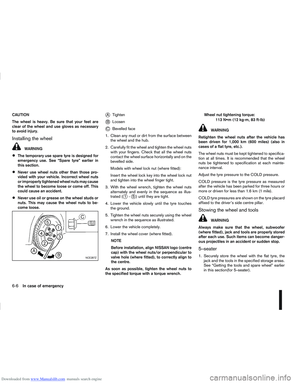
jATighten
jB Loosen
jC Bevelled face
1. Clean any mud or dirt from the surface between the wheel and the hub.
2. Carefully fit the wheel and tighten the wheel nuts with your fingers. Check that all the wheel nuts
contact the wheel surface horizontally and on the
bevelled side.
Models with wheel lock nut (where fitted):
Insert the wheel lock key into the wheel lock nut
and tighten into the wheel finger tight.
3. With the wheel wrench, tighten the wheel nuts alternately and evenly in the sequence as illus-
trated (
j1-j5 ) until they are tight.
4. Lower the vehicle slowly until the tyre touches the ground.
5. Tighten the wheel nuts securely using the wheel wrench in the sequence as illustrated.
6. Lower the vehicle completely.
7. Install the wheel cover (where fitted). NOTE
Before installation, align NISSAN logo (centre
cap) with the wheel nuts/or perpendicular to
valve hole (where fitted), to correctly align to
the centre.
As soon as possible, tighten the wheel nuts to
the specified torque with a torque wrench. Wheel nut tightening torque:
113 (12 kg-m, 83 ft-lb)
WARNING
Retighten the wheel nuts after the vehicle has
been driven for 1,000 km (600 miles) (also in
cases of a flat tyre, etc.).
The wheel nuts must be kept tightened to specifica-
tion at all times. It is recommended that the wheel
nuts be tightened to specification at each mainte-
nance interval.
Adjust the tyre pressure to the COLD pressure.
COLD pressure is the tyre pressure as measured
after the vehicle has been parked for three hours or
more or driven for less than 1.6 km (1 mile).
COLD tyre pressures are shown on the tyre placard
affixed to the driver’s side centre pillar.
Stowing the wheel and tools
WARNING
Always make sure that the wheel, subwoofer
(where fitted), jack and tools are properly stored
after each use. Such items can become danger-
ous projectiles in an accident or sudden stop.
5–seater
1. Securely store the wheel with the flat tyre, the jack and the tools in the specified storage areas.
See “Getting the tools and spare wheel” earlier
in this section(for 5–seater).NCE287Z
6-6In case of emergency
Page 214 of 297

Downloaded from www.Manualslib.com manuals search engine 2. Store the subwoofer (where fitted) as it was origi-nally installed.
3. Install the retainer and replace the floor cover.
7–seater
1. Store the tools in the specified areas.
2. Firmly pull down the third row seat and make sure it locks into the locking latches on both sides
under the seat.
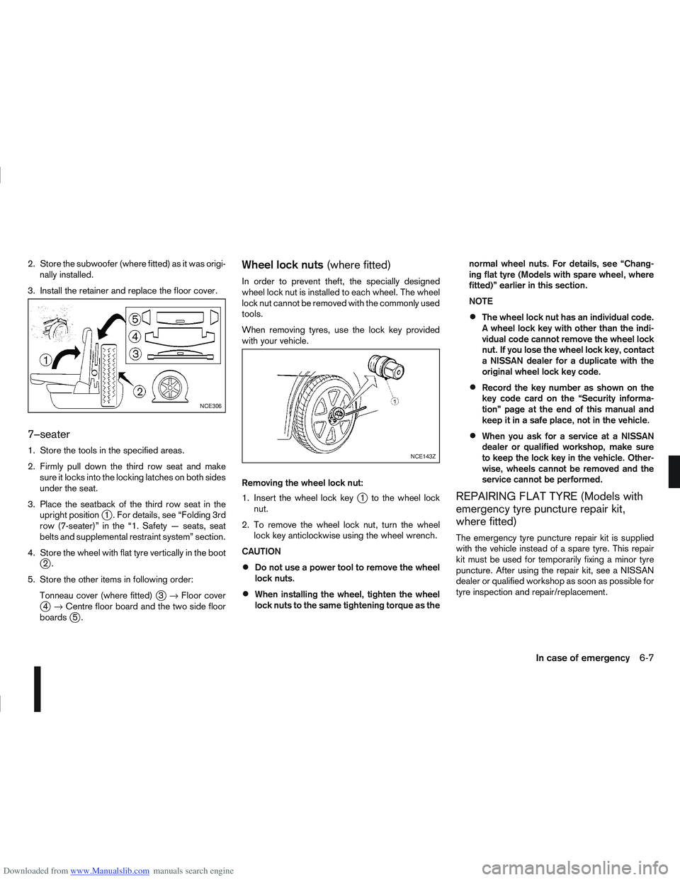
3. Place the seatback of the third row seat in the upright position
j1 . For details, see “Folding 3rd
row (7-seater)” in the “1. Safety — seats, seat
belts and supplemental restraint system” section.
4. Store the wheel with flat tyre vertically in the boot
j2.
5. Store the other items in following order: Tonneau cover (where fitted)
j3→ Floor coverj4→ Centre floor board and the two side floor
boardsj5.
Wheel lock nuts (where fitted)
In order to prevent theft, the specially designed
wheel lock nut is installed to each wheel. The wheel
lock nut cannot be removed with the commonly used
tools.
When removing tyres, use the lock key provided
with your vehicle.
Removing the wheel lock nut:
1. Insert the wheel lock key
j1 to the wheel lock
nut.
2. To remove the wheel lock nut, turn the wheel lock key anticlockwise using the wheel wrench.
CAUTION
Do not use a power tool to remove the wheel
lock nuts.
When installing the wheel, tighten the wheel
lock nuts to the same tightening torque as the normal wheel nuts. For details, see “Chang-
ing flat tyre (Models with spare wheel, where
fitted)” earlier in this section.
NOTE
The wheel lock nut has an individual code.
A wheel lock key with other than the indi-
vidual code cannot remove the wheel lock
nut. If you lose the wheel lock key, contact
a NISSAN dealer for a duplicate with the
original wheel lock key code.
Record the key number as shown on the
key code card on the “Security informa-
tion” page at the end of this manual and
keep it in a safe place, not in the vehicle.
When you ask for a service at a NISSAN
dealer or qualified workshop, make sure
to keep the lock key in the vehicle. Other-
wise, wheels cannot be removed and the
service cannot be performed.
REPAIRING FLAT TYRE (Models with
emergency tyre puncture repair kit,
where fitted)
The emergency tyre puncture repair kit is supplied
with the vehicle instead of a spare tyre. This repair
kit must be used for temporarily fixing a minor tyre
puncture. After using the repair kit, see a NISSAN
dealer or qualified workshop as soon as possible for
tyre inspection and repair/replacement.
NCE306
NCE143Z
In case of emergency6-7