2009 NISSAN QASHQAI heating
[x] Cancel search: heatingPage 49 of 297

Downloaded from www.Manualslib.com manuals search engine 2Instruments and controls
Instruments and controls
Meters and gauges .................................................. 2-2
Speedometer...................................................... 2-2
Fuel gauge ......................................................... 2-2
Tachometer ........................................................ 2-2
Engine coolant temperature gauge ...................... 2-2
Warning/indicator lights and audible reminders ........ 2-3 Checking bulbs .................................................. 2-3
Warning lights .................................................... 2-3
Indicator lights .................................................... 2-7
Audible reminders............................................... 2-9
Vehicle information display ....................................... 2-11 Warnings and alerts............................................ 2-12
Odometer/twin trip odometer .............................. 2-16
Brightness control .............................................. 2-16
Trip computer ..................................................... 2-16
Settings menu .................................................... 2-18
Cruise control/Speed limiter indicator (where
fitted).................................................................. 2-21
Wiper and washer switch ........................................ 2-21 Windscreen ........................................................ 2-22
Rear window ...................................................... 2-23
Defogger switch ...................................................... 2-23 Rear window defogger ....................................... 2-23
Outside mirror defogger (where fitted) ................ 2-24
Headlight and turn signal switch............................... 2-24 Xenon headlights (where fitted) ........................... 2-24
Headlight switch ................................................. 2-24
Turn signal switch ............................................... 2-26
Fog light switch ....................................................... 2-26 Front fog light (where fitted) ................................ 2-26 Rear fog light ...................................................... 2-27
Headlight aiming control .......................................... 2-27 Headlight aiming control switch (where fitted) ..... 2-27
Automatic aiming control (xenon headlights) ........ 2-27
Headlight cleaner (where fitted) ............................... 2-28
Hazard warning flasher switch ................................. 2-28
Horn ........................................................................\
2-29
Seat heating (where fitted) ....................................... 2-29
Power outlet ............................................................ 2-30
Storage ................................................................... 2-31 Storage trays ...................................................... 2-31
Glove box ........................................................... 2-31
Console box ....................................................... 2-32
Cup holders ....................................................... 2-32
Bottle holder ....................................................... 2-32
Map pocket (where fitted) ................................... 2-32
Seat pocket (where fitted)................................... 2-32
Roof rail (where fitted) ........................................ 2-32
Rear parcel shelf (where fitted) ................................ 2-33
Tonneau cover (where fitted).................................... 2-33
Windows ................................................................. 2-34 Power windows .................................................. 2-34
C-View® glass roof (where fitted) ............................ 2-36 Sunshade operation ............................................ 2-36
System reinitialisation.......................................... 2-37
Interior lights ............................................................ 2-37 Front Room light ................................................. 2-37
Map lights (where fitted) ..................................... 2-38
Rear room/reading light ...................................... 2-38
Luggage compartment light ................................ 2-38
Page 78 of 297

Downloaded from www.Manualslib.com manuals search engine To sound the horn, push the centre pad areaj1of
the steering wheel. The front seats are warmed by built-in heaters.
The switches are located on the centre console and
can be operated independently from each other (
jA
for the left-hand side seat,jB for the right-hand side
seat).
1. Turn the ignition switch to the ON position.
NOTE
The seat heater can only be activated when
the ignition switch is in the ON position.
2. Start the engine.
3. Select the heat range:
Press the forward part of the switch (large
dot) to activate the “HIGH” heat setting.
Press the rear part of the switch (small dot) to
activate the “LOW” heat setting.
For no heat, the switch has a central “OFF”
position between “HIGH” and “LOW”. 4. The seat heater switches illuminate when either
heat setting is selected and will remain on as
long as the switch is on.
5. When the vehicle’s interior has warmed-up, or before you leave the vehicle, be sure to turn the
seat heater system off.
CAUTION
Do not use the seat heater system for a long
period of time when the engine is not running,
otherwise the battery could run down.
Do not put anything on the seat that insulates
the heat, such as a blanket, cushion, seat
cover, etc. Otherwise, the seat may overheat.
Do not place anything hard or heavy on the
seat or pierce it with a pin or similar object.
This may damage the heater.
Any liquid spilled on a heated seat should be
removed immediately with a dry cloth.
When cleaning the seat, never use benzine,
thinner or any similar materials.
If any abnormalities are found or the heating
does not operate, turn off the switch and have
the system checked by a NISSAN dealer or
qualified workshop.
NIC1352ZNIC1429
HORN SEAT HEATING (where fitted)
Instruments and controls2-29
Page 93 of 297
![NISSAN QASHQAI 2009 Owners Manual Downloaded from www.Manualslib.com manuals search engine – The message [Single door unlock] appears inthe vehicle information display.
– Only the driver’s door unlocks.
– The direction indicat NISSAN QASHQAI 2009 Owners Manual Downloaded from www.Manualslib.com manuals search engine – The message [Single door unlock] appears inthe vehicle information display.
– Only the driver’s door unlocks.
– The direction indicat](/manual-img/5/56767/w960_56767-92.png)
Downloaded from www.Manualslib.com manuals search engine – The message [Single door unlock] appears inthe vehicle information display.
– Only the driver’s door unlocks.
– The direction indicators flash twice, quickly.
2. Push the “UNLOCK” button
on the integrated
keyfob again.
– All doors unlock.
– The direction indicators flash twice.
Auto-relock:
An auto-relock function will operate 2 minutes after
a full or partial unlock, if no further user action is
taken. The auto-relock will be cancelled if any door
is opened or the key is inserted into the ignition.
KEYFOB OPERATION FAILURE
The keyfob may not work properly if:
The keyfob battery is low. See “Integrated key-
fob/Intelligent Key battery replacement” in the
“8. Maintenance and do-it-yourself” section for
keyfob battery replacement instructions and the
required battery type.
The locking/unlocking system has been used
continuously. An anti lock-abuse system pre-
vents the lock motors from overheating and dis-
ables the keyfob locking operation for a short
period of time if the system is used continuously.
The door handle is being pulled while the
keyfob is being operated.
The vehicle’s battery is dead. NOTE
See Intelligent Key detection warning, Intelligent
Key low battery warning or Intelligent Key system
fault warning in “Vehicle information display” ear-
lier in this section for more information.
The Intelligent Key system is a convenient keyless
entry system that allows you to operate your vehicle
without using an actual key.
WARNING
Radio waves could adversely affect electric medi-
cal equipment. Those who use a pacemaker
should contact the electric medical equipment
manufacturer for the possible influences before
use.
INTELLIGENT KEY OPERATING
RANGE
The Intelligent Key functions can only be used when
the Intelligent Key is within the specified operating
range from the request switch
j1.
When the Intelligent Key battery is discharged or
strong radio waves are present near the operating
location, the Intelligent Key system’s operating
range becomes narrower, and the Intelligent Key
may not function properly.
NPA1042NPA1018
INTELLIGENT KEY SYSTEM
(where fitted)
3-6Pre-driving checks and adjustments
Page 119 of 297

Downloaded from www.Manualslib.com manuals search engine SIDE AND CENTRE VENTS
The direction of the air flow can be adjusted byjA
opening,jB closing orjC adjusting.
HIGH LEVEL VENT (where fitted)
Press thebutton to switch the mild air flow from
the upper vent on or off. Use the upper vent on hot
days to let cool air flow along the roof to the rear
passengers; and on cold days to improve the de-
frosting or defogging of the windows with warm air.
WARNING
Do not leave children or adults who would
normally require the support of others alone
in your vehicle. Pets should not be left alone
either. On hot, sunny days, temperatures in a
closed vehicle could quickly become high
enough to cause severe or possibly fatal inju-
ries to people or animals.
Do not use the recirculation mode for long
periods as it may cause the interior air to be-
come stale and the windows to fog up. It is
recommended that you use the outside air
mode in cold weather to keep the windows
clear.
Do not adjust the positioning of the heating/
ventilation or air conditioning controls while
driving.
NOTE
Condensation forms inside the air condition-
ing unit when the air conditioner is running,
and is safely discharged underneath your ve-
hicle.
Traces of water on the ground are therefore
normal.
Models with Stop/Start System:
Whilst the engine is stopped by the Stop/Start
System, selecting airflow to the front defog-
ger or switching on the rear defogger will
cause the engine the be automatically re-
started. Whilst the engine is running, selecting airflow
to the front defogger or switching on the rear
defogger will prevent the Stop/Start System
automatically stopping the engine.
The Stop/Start System will prevent unneces-
sary fuel consumption and exhaust emis-
sions. When the engine is stopped by the
Stop/Start System heater and air conditioner
performance may be reduced. To keep full
heater and air conditioner performance, re-
start the engine by pressing the Stop/Start
System OFF switch, or by turning the ignition
switch.
For more information on the Stop/Start Sys-
tem, see “Stop/Start System (where fitted)”
in the “5. Starting and driving” section.
NAA945Z
NAA1150
VENTS
HEATER AND AIR CONDITIONER
OPERATION
4-12Display screen, heater and air conditioner, and audio system
Page 121 of 297

Downloaded from www.Manualslib.com manuals search engine Air flow control dial:
Use this dial to manually select the air flow from the
air outlets as described below.
: Air flows from centre and side vents.
: Air flows from centre, side vents and floor
outlets.
: Air flows mainly from floor outlets.
: Air flows from the defogger outlets and floor
outlets.
: Air flows mainly from defogger outlets.
Air recirculation button
m:
Outside air circulation
Press the air recirculation () button to the
“OFF” position to draw outside air into the pas-
senger compartment (the indicator light goes
off). Use the “OFF” position for normal heating
ventilation, or air conditioner (where fitted) op-
eration.
Air recirculation
Press the air recirculation (
) button to the
“ON” position (the indicator light goes on). Use
the “ON” position in situations such as: driving
on a dust raised road, avoiding traffic fumes or
having maximum cooling from the air conditioner
(where fitted).
If the windows fog up, switch on the air condi-
tioning (where fitted). A/C (Air Conditioner) button (where fitted):
Press the A/C button to turn the air conditioner on
or off. When the air conditioner is on, the A/C indi-
cator light illuminates.
Operation
The heater and air conditioner operate when the
engine is running. The air blower will operate even if
the engine is turned off and the ignition switch is in
the ON position.
NOTE
The air conditioner cooling function operates only
when the engine is running and the fan is acti-
vated.
1. Press the air recirculation (
) button to the
“OFF” position.
2. Turn the airflow control dial for: – Cooling: select the
orposition.
– Heating: select the
orposition.
– Heating and defogging : select the
po-
sition.
– Ventilation : select the
orposition.
– Windscreen defogging : select the
po-
sition
3. Turn the fan speed control dial to the desired position.
4. Turn the temperature control dial to the desired position. NOTE
When selecting the
orposition, turn
the temperature control dial to the desired
position between the middle and the maxi-
mum “HOT” (right) position.
5. Press the A/C button (where fitted) to the “ON” position and the indicator light will come on.
Switch this mode on for dehumidified heating or
cooling.
NOTE
The air conditioner mode is used to cool and
dehumidify. For quick cooling when the out-
side temperature is high, select the air recir-
culation mode position (
). Be sure to re-
turn to the outside air mode to avoid windows
from fogging-up and interior air from becom-
ing stale.
A visible mist may be seen coming from the
vents in hot, humid conditions as the air is
cooled rapidly this is not a malfunction.
For quick heating, press the air recirculation
() button to the “ON” position. Be sure to
return to the “OFF” position for normal heat-
ing (no indicator light) in order to avoid win-
dow fog and stale interior.
To quickly defrost/defog the windscreen,
turn:
1) The airflow control dial to
position.
2) The fan speed control dial to speed posi- tion 4.
4-14Display screen, heater and air conditioner, and audio system
Page 122 of 297

Downloaded from www.Manualslib.com manuals search engine 3) The temperature control dial to the maxi-mum “HOT” (right) position.
Operating tips
In order to improve the heater operation, clear
the snow and ice from the wiper blade and air
inlet in front of the windscreen.
After parking in the sun, drive for two or three
minutes with the windows open to vent hot air
from the passenger compartment. Then close
the windows to allow the acceleration of the air
conditioner’s cooling operation.
Keep the windows closed while the air condi-
tioner is operating.
The air conditioning system should be operated
for about 10 minutes, at least once a month. This
helps prevent damage to the system due to lack
of lubrication.
If the coolant temperature gauge exceeds the
“HOT” position, turn the air conditioner off. For
additional information, see “Engine overheat” in
the “6. In case of emergency” section.
If the engine coolant reaches an extremely high
temperature, the air conditioning system will au-
tomatically turn off. This may happen for example
if the engine runs at idle speed for a long time on
a hot day.
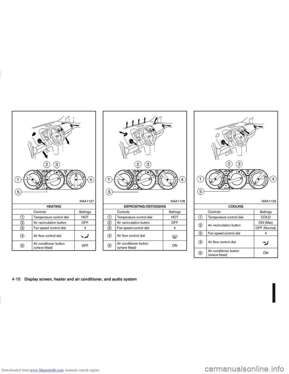
Quick reference charts
The following charts show the button, air intake and
dial positions for MAXIMUM AND QUICK heating,
cooling or defrosting. NOTE
The air recirculation mode should not be selected
for either heating or defrosting.
Display screen, heater and air conditioner, and audio system4-15
Page 123 of 297

Downloaded from www.Manualslib.com manuals search engine m
NAA1127
HEATING
Controls Settings
j1 Temperature control dial HOT
j2 Air recirculation button OFF
j3 Fan speed control dial 4
j4 Air flow control dialm
j5Air conditioner button
(where fitted) OFF
m
NAA1128
DEFROSTING/DEFOGGING
Controls Settings
j1 Temperature control dial HOT
j2 Air recirculation button OFF
j3 Fan speed control dial 4
j4 Air flow control dialm
j5Air conditioner button
(where fitted) ON
m
NAA1129
COOLING
Controls Settings
j1 Temperature control dial COLD
j2 Air recirculation buttonON (Max)
OFF (Normal)
j3 Fan speed control dial 4
j4 Air flow control dialm
j5Air conditioner button
(where fitted) ON
4-16Display screen, heater and air conditioner, and audio system
Page 125 of 297

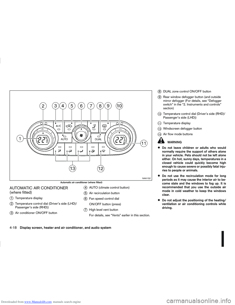
Downloaded from www.Manualslib.com manuals search engine AUTOMATIC AIR CONDITIONER
(where fitted)
j
1Temperature display
j2Temperature control dial (Driver’s side (LHD)/
Passenger’s side (RHD))
j3Air conditioner ON/OFF button
j4AUTO (climate control button)
j5Air recirculation button
j6Fan speed control dial
ON/OFF button (press)
j7High level vent button
For details, see “Vents” earlier in this section.
j8DUAL zone control ON/OFF button
j9Rear window defogger button (and outside
mirror defogger (For details, see “Defogger
switch” in the “2. Instruments and controls”
section)
j10Temperature control dial (Driver’s side (RHD)/
Passenger’s side (LHD))
j11Temperature display
j12Windscreen defogger button
j13Air flow mode buttons
WARNING
Do not leave children or adults who would
normally require the support of others alone
in your vehicle. Pets should not be left alone
either. On hot, sunny days, temperatures in a
closed vehicle could quickly become high
enough to cause severe or possibly fatal inju-
ries to people or animals.
Do not use the recirculation mode for long
periods as it may cause the interior air to be-
come stale and the windows to fog up. It is
recommended that you use the outside air
mode in cold weather to keep the windows
clear.
Do not adjust the positioning of the heating/
ventilation or air conditioning controls while
driving.
NAA1152
Automatic air conditioner (where fitted)
4-18Display screen, heater and air conditioner, and audio system