2009 NISSAN MURANO fuse
[x] Cancel search: fusePage 11 of 443

Black plate (8,1)
Model "Z51-D" EDITED: 2007/ 10/ 2
SSI0376
1. Headlight aiming control* (P.2-34)
2. Side ventilator (P.4-25)
3. Power lift gate switch* (P.3-18)
4. Headlight, fog light* and turn signal switch
(P.2-32)
5. Fuel-filler door opener switch (P.3-23)6. Steering-wheel-mounted controls (left side)*
— Audio control* (P.4-60)
— Bluetooth
®Hands-Free Phone System control*
(P.4-75)
7. Meters and gauges (P.2-4)8. Steering wheel
— Horn (P.2-37)
— Driver supplemental air bag (P.1-41)
— Power steering system (P.5-25)
9. Steering-wheel-mounted controls (right side)
— Cruise control switches (P.5-18)
10. Wiper and washer switch (P.2-28)
11. Push-button ignition switch (P.5-8)
12. Center ventilator (P.4-25)
13. Center display (P.4-26, P.4-31)/Center color dis-
play* (P.4-2)/Navigation system**
14. Heater/air conditioner or
Center multi-function control panel*
— Navigation system**
— Vehicle information and setting buttons (P.4-8)
— Bluetooth
®Hands-Free Phone System (P.4-75)
— Audio system (P.4-31)
15. Hazard warning flasher switch (P.2-36)
16. Front passenger supplemental air bag (P.1-41)
17. Vehicle Dynamic Control (VDC) OFF switch
(P.2-39, 5-27)
18. Power lift gate main switch (P.3-18)
19. Power seatback switch* (P.1-6)
20. Fuse box cover (P.8-21)
21. Parking brake (P.5-17)
22. Tilting telescopic steering wheel lever or switch
(P.3-25)
23. Key port (P.5-11)
24. Audio system (P.4-31)
— Clock (P.2-38)
25. Heated seat switch* (P.2-37)
26. Selector lever (P.5-13)
INSTRUMENT PANEL
0-6Illustrated table of contents
Page 14 of 443

Black plate (11,1)
Model "Z51-D" EDITED: 2007/ 10/ 2
SDI2172
VQ35DE ENGINE
1. Power steering fluid reservoir (P.8-11)
2. Drive belt location (P.8-15)
3. Engine oil filler cap (P.8-8)
4. Brake fluid reservoir (P.8-12)
5. Air cleaner (P.8-16)6. Fuse/fusible link holder (P.8-20)
7. Window washer fluid reservoir (P.8-12)
8. Engine coolant reservoir (P.8-7)
9. Radiator filler cap (P.8-7)
10. Engine oil dipstick (P.8-8)
11. Battery (P.8-13)
ENGINE COMPARTMENT
Illustrated table of contents0-9
Page 72 of 443

Black plate (70,1)
Model "Z51-D" EDITED: 2007/ 10/ 2
SSI0376
1. Headlight aiming control*
2. Side ventilator
3. Power lift gate switch*
4. Headlight, fog light* and turn signal switch
5. Fuel-filler door opener switch6. Steering-wheel-mounted controls (left side)*
— Audio control*
— Bluetooth
®Hands-Free Phone System control*
7. Meters and gauges8. Steering wheel
— Horn
— Driver supplemental air bag
— Power steering system
9. Steering-wheel-mounted controls (right side)
— Cruise control switches
10. Wiper and washer switch
11. Push-button ignition switch
12. Center ventilator
13. Center display/Center color display*/Navigation
system**
14. Heater/air conditioner or
Center multi-function control panel*
— Navigation system**
— Vehicle information and setting buttons
— Bluetooth
®Hands-Free Phone System
— Audio system
15. Hazard warning flasher switch
16. Front passenger supplemental air bag
17. Vehicle Dynamic Control (VDC) OFF switch
18. Power lift gate main switch
19. Power seatback switch
20. Fuse box cover
21. Parking brake
22. Tilting telescopic steering wheel lever or switch
23. Key port
24. Audio system
— Clock
25. Heated seat switch*
26. Selector lever
27. Front passenger air bag status light
28. Power outlet
INSTRUMENT PANEL
2-2Instruments and controls
Page 110 of 443
Black plate (108,1)
Model "Z51-D" EDITED: 2007/ 10/ 2
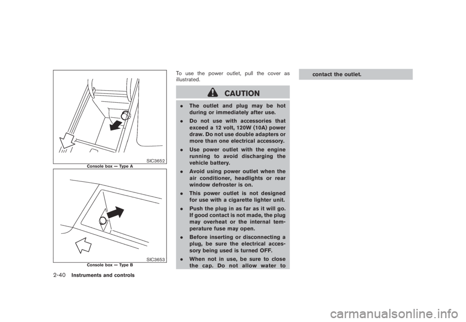
SIC3652Console box — Type A
SIC3653Console box — Type B
To use the power outlet, pull the cover as
illustrated.
CAUTION
.The outlet and plug may be hot
during or immediately after use.
.Do not use with accessories that
exceed a 12 volt, 120W (10A) power
draw. Do not use double adapters or
more than one electrical accessory.
.Use power outlet with the engine
running to avoid discharging the
vehicle battery.
.Avoid using power outlet when the
air conditioner, headlights or rear
window defroster is on.
.This power outlet is not designed
for use with a cigarette lighter unit.
.Push the plug in as far as it will go.
If good contact is not made, the plug
may overheat or the internal tem-
perature fuse may open.
.Before inserting or disconnecting a
plug, be sure the electrical acces-
sory being used is turned OFF.
.When not in use, be sure to close
the cap. Do not allow water tocontact the outlet.
2-40Instruments and controls
Page 160 of 443
Black plate (160,1)
Model "Z51-D" EDITED: 2007/ 10/ 2
The automatic drive positioner system has two
features:
.Entry/exit function
.Memory storage
ENTRY/EXIT FUNCTION
This system is designed so that the driver’s seat
and steering column will automatically move
when the selector lever is in the P (Park)
position. This allows the driver to get into and
out of the driver’s seat more easily.
The driver’s seat will slide backward and the
steering wheel will move up when the driver’s
door is opened with the ignition switch in the
LOCK position and the key not inserted in the
key port.
The driver’s seat and steering wheel will return
to the previous positions when the ignition
switch is pushed to the ACC position.
The driver’s seat will not return to the previous
positions if the seat or steering adjusting switch
is operated when the seat is at the exit position.
Cancel or activate entry/exit function
The selector lever must be in the P (Park)
position with the ignition switch in the OFF
position after the driver’s door is opened.
The entry/exit function can be activated orcanceled by pressing and holding the SET
switch for more than 10 seconds.
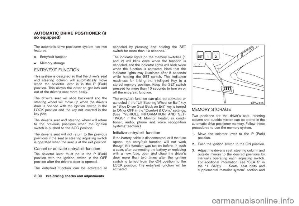
The indicator lights on the memory switches (1
and 2) will blink once when the function is
canceled, and the indicator lights will blink twice
when the function is activated. Note that the
indicator lights may illuminate after 5 seconds
while holding the SET switch. This indicates
readiness for linking the Intelligent Key to a
stored memory position. Keep the SET switch
pressed for more than 10 seconds to turn on or
off the entry/exit function.
The entry/exit function can also be activated or
canceled if the “Lift Steering Wheel on Exit” key
or “Slide Driver Seat Back on Exit” key is turned
to ON or OFF in the “Comfort & Conv.” settings.
(See “VEHICLE INFORMATION AND SET-
TINGS” in the “4. Monitor, heater, air condi-
tioner, audio, phone and voice recognition
systems” section.)
Initialize entry/exit function
If the battery cable is disconnected, or if the fuse
opens, the entry/exit function will not work
though this function was set on before. In such
a case, after connecting the battery or replacing
with a new fuse, open and close the driver’s
door more than two times after the ignition
switch is turned from the ON position to the
LOCK position. The entry/exit function will be
activated.
SPA2445
MEMORY STORAGE
Two positions for the driver’s seat, steering
column and outside mirrors can be stored in the
automatic drive positioner memory. Follow these
procedures to use the memory system.
1. Move the selector lever to the P (Park)
position.
2. Push the ignition switch to the ON position.
3. Adjust the driver’s seat, steering column and
outside mirrors to the desired positions by
manually operating each adjusting switch.
For additional information, see “SEATS” in
the “1. Safety — Seats, seat belts and
supplemental restraint system” section and
AUTOMATIC DRIVE POSITIONER (if
so equipped)
3-30Pre-driving checks and adjustments
Page 161 of 443
Black plate (161,1)
Model "Z51-D" EDITED: 2007/ 10/ 2
“TILTING TELESCOPIC STEERING COL-
UMN” earlier in this section and “OUTSIDE
MIRRORS” earlier in this section.
4. Push the SET switch and, within 5 seconds,
push the memory switch (1 or 2) .
The indicator light for the pushed memory
switch will stay on for approximately 5
seconds after pushing the switch.
If memory is stored in the same memory
switch, the previous memory will be deleted.
Linking key to a stored memory position
The key can be linked to a stored memory
position with the following procedure.
1. Follow one of the steps for storing a memory
position.
.While the indicator light for the memory
switch being set is illuminated for 5 sec-
onds, push the
button on the key.
.Push the ignition switch to the OFF position,
and then push the SET switch. Push the
button while pushing the memory
button while the indicator light stays on for
approximately 5 seconds.
If the indicator light blinks, the key is linked to
that memory setting.
Push the ignition switch to the OFF position, andthen push the
button on the key. The
driver’s seat, steering wheel and outside mirrors
will move to the memorized position.
Confirming memory storage
.Push the ignition switch to the ON position
and push the SET switch. If the main
memory has not been stored, the indicator
light will come on for approximately 0.5
second. When the memory has stored in
position, the indicator light will stay on for
approximately 5 seconds.
.If the battery cable is disconnected, or if the
fuse opens, the memory will be canceled. In
this case, reset the desired position using
the previous procedure.
.If optional keys are added to your vehicle,
the memory storage procedure to switch 1
or 2 and linking key procedure to a stored
memory position should be performed again
for each key. For additional Intelligent Key
information, see “KEYS” earlier in this
section.
Selecting the memorized position
1. Move the selector lever to the P (Park)
position.
2. Use one of the following methods to move
the driver’s seat, the outside mirrors and the
steering wheel..Push the ignition switch to the ON
position and push the memory switch
(1 or 2) .
.Within 45 seconds of opening the
driver’s door, push the memory switch
(1 or 2) .
The driver’s seat, steering column and
outside mirrors will move to the memorized
position with the indicator light flashing, and
then the light will stay on for approximately 5
seconds.
SYSTEM OPERATION
The automatic drive positioner system will not
work or will stop operating under the following
conditions:
.When the vehicle speed is above 4 MPH (7
km/h) (entry/exit function) .
.When the vehicle is driven (memory sto-
rage) .
.When the adjusting switch for the driver’s
seat and steering column is turned on while
the automatic drive positioner is operating.
.When the seat, steering column and outside
mirrors have already been moved to the
memorized position.
.When no position is stored in the memory
switch.
Pre-driving checks and adjustments3-31
Page 205 of 443
Black plate (203,1)
Model "Z51-D" EDITED: 2007/ 10/ 2
buttons*1to*6until a beep sound is
heard. (The radio mutes when the select
button is pushed.)
4. The channel indicator will then come on and
the sound will resume. Memorizing is now
complete.
5. Other buttons can be set in the same
manner.
If the battery cable is disconnected, or if the fuse
blows, the radio memory will be erased. In that
case, reset the desired stations.
Compact Disc (CD) changer operation
Push the ignition switch to the ACC or ON
position, push the LOAD button and insert the
compact disc into the slot with the label side
facing up. The compact disc will be guided
automatically into the slot and start playing.
After loading the disc, the number of tracks on
the disc and the play time will appear on the
display.
If the radio is already operating, it will auto-
matically turn off and the compact disc will play.
If the system has been turned off while the
compact disc was playing, pushing the ON·-
OFF/VOL control knob will start the compact
disc.
CD LOAD:
To insert a CD in the CD changer, push the
LOAD button for less than 1.5 seconds. Select
the loading position by pushing the CD insert
select button
*1to*6, then insert the CD.
To insert 6 CDs to the CD changer in
succession, push the LOAD button for more
than 1.5 seconds.
The inserted slot numbers will illuminate on the
display.
PLAY:
When the DISC (CD play) button is pushed with
the system off and the compact disc loaded, the
system will turn on and the compact disc will
start to play.
When the DISC button is pushed with the
compact disc loaded and the radio playing, the
radio will automatically be turned off and the
compact disc will start to play.
When the DISC button is pushed while a CD is
loaded and a medium is played using the
auxiliary input jacks, you can toggle back and
forth between CD and medium.
CD PLAY INFORMATION:
When the DISP button is pushed for less than
1.5 seconds while the CD is being played, the
disc information display will change as follows:
CD:
CD with MP3 or WMA:
FF (Fast Forward) , REW (Re-
wind)/APS (Automatic Pro-
gram Search) FF, APS REW:
When the
(fast forward) or(rewind)
button is pushed for more than 1.5 seconds
while the compact disc is being played, the
compact disc will play while fast forwarding or
rewinding. When the button is released, the
compact disc will return to normal play speed.
When the
orbutton is pushed for less
than 1.5 seconds while the compact disc is
being played, the next track or the beginning of
Monitor, heater, air conditioner, audio, phone and voice recognition systems4-41
Page 210 of 443
Black plate (208,1)
Model "Z51-D" EDITED: 2007/ 10/ 2
low frequencies and to stop at the next
broadcasting station.
.For XM satellite radio
Push the SEEK·CAT or TRACK button
orto tune to the first channel of the
next or previous category.
During satellite radio reception, the following
notices will be displayed under certain condi-
tions.
.NO SIGNAL (No signal is received while the
SAT tuner is connected.)
.OFF AIR (Broadcasting signed off)
.ANTENNA ERROR (Antenna connection
error)
.LOADING (When the initial setting is
performed)
.UPDATING (When the satellite radio sub-
scription is not active)
.INVALID CH (Invalid channel is received.)
SCAN tuning:
Push the SCAN tuning button to tune from low
to high frequencies and stops at each broad-
casting station for 5 seconds. Pushing the
button again during this 5 seconds period will
stop SCAN tuning and the radio will remaintuned to that station.
If the SCAN tuning button is not pushed within 5
seconds, SCAN tuning moves to the next
station.
*1to*6Station memory operations:
Twelve stations/channels can be set for the FM
band (6 for FM1, 6 for FM2) and the SAT radio
(6 for SAT1, 6 for SAT2) , and 6 stations can be
set for the AM band.
1. Choose the radio band using the radio band
select button.
2. Tune to the desired station using the SEEK,
SCAN or TUNE button.
3. Select the desired station/channel and keep
pushing any of the desired station preset
buttons
*1to*6until a beep sound is
heard. (The radio mutes when the select
button is pushed.)
4. The channel indicator will then come on and
the sound will resume. Memorizing is now
complete.
5. Other buttons can be set in the same
manner.
If the battery cable is disconnected, or if the fuse
blows, the radio memory will be erased. In that
case, reset the desired stations.Text:
When the “Text” key is selected with the multi-
function controller on the display and then the
ENTER button is pushed while the satellite radio
is being played, the text information will be
displayed on the screen.
.CH Name
.Category
.Name
.Title
.Other
Compact Disc (CD) player/changer op-
eration
Push the ignition switch to the ACC or ON
position, push the LOAD button (if so equipped)
and insert the compact disc into the slot with the
label side facing up. The compact disc will be
guided automatically into the slot and start
playing.
After loading the disc, the number of tracks on
the disc and the play time will appear on the
display.
If the radio is already operating, it will auto-
matically turn off and the compact disc will play.
If the system has been turned off while the
compact disc was playing, pushing the ON·-
4-46Monitor, heater, air conditioner, audio, phone and voice recognition systems