2009 NISSAN MURANO door lock
[x] Cancel search: door lockPage 97 of 443

Black plate (95,1)
Model "Z51-D" EDITED: 2007/ 10/ 2
The alarm is activated by:
.Unlocking the door without using the button
on the key, the request switch (if so
equipped) or the key. (Even if the door is
opened by releasing the door inside lock
knob, the alarm will activate.)
.Opening the hood.
How to stop an activated alarm
The alarm will stop by unlocking a door by
pushing the unlock buttonon the key,
pushing the request switch or using the key.
If the system does not operate as de-
scribed above, have it checked by a
NISSAN dealer.
NISSAN VEHICLE IMMOBILIZER SYS-
TEM
The NISSAN Vehicle Immobilizer System will not
allow the engine to start without the use of the
registered key.Never leave these keys in the
vehicle.
Statement related to section 15 of FCC
rules for NISSAN Vehicle Immobilizer
System (CONT ASSY - CARD SLOT)
This device complies with part 15 of the
FCC Rules and RSS-210 of Industry Cana-
da. Operation is subject to the following
two conditions;(1) This device may not cause harmful
interference, and (2) this device must
accept any interference received, including
interference that may cause undesired
operation of the device.
CHANGES OR MODIFICATIONS NOT EX-
PRESSLY APPROVED BY THE PARTY
RESPONSIBLE FOR COMPLIANCE COULD
VOID THE USER’S AUTHORITY TO OPER-
ATE THE EQUIPMENT.
SIC1699A
Security indicator light
The security indicator light*Aindicates the
status of the NISSAN Vehicle Immobilizer
System.
The light blinks after the ignition switch was in
the ACC, OFF and LOCK position. This function
indicates the security systems equipped on the
vehicle are operational.
If the NISSAN Vehicle Immobilizer System is
malfunctioning, this light will remain on while the
ignition switch is in the ON position.
If the light still remains on and/or the
engine will not start, see a NISSAN dealer
for NISSAN Vehicle Immobilizer System
Instruments and controls2-27
Page 104 of 443

Black plate (102,1)
Model "Z51-D" EDITED: 2007/ 10/ 2
SIC3670
Headlight beam select
*1To select the low beam, put the lever in the
neutral position as shown.
*2To select the high beam, push the lever
forward while the switch is in the
position. Pull it back to select the low beam.
*3Pulling the lever toward you will flash the
headlight high beam even when the head-
light switch is in the OFF position.
Battery saver system
A chime will sound when the driver side door is
opened with the light switch in theorposition and the ignition switch in the ACC,
OFF or LOCK position.When the headlight switch is in the
orposition while the ignition switch is in the ON
position, the lights will automatically turn off 5
minutesaftertheignitionswitchhasbeen
pushed to the OFF position.
When the headlight switch remains in the
orposition after the lights automatically
turn off, the lights will turn on when the ignition
switch is pushed to the ON position.
CAUTION
.When you turn on the headlight
switch again after the lights auto-
matically turn off, the lights will not
turn off automatically. Be sure to
turn the light switch to the OFF
position when you leave the vehicle
for extended periods of time, other-
wise the battery will be discharged.
.Never leave the light switch on
when the engine is not running for
extended periods of time even if the
headlights turn off automatically.
SIC2275
Headlight aiming control (if so equipped)
Depending on the number of occupants in the
vehicle and the load it is carrying, the headlight
axis may be higher than desired. If the vehicle is
traveling on a hilly road, the headlights may
directly hit the rearview mirror of the vehicle
ahead or the windshield of the oncoming
vehicle. The light axis can be lowered with the
operation of the switch.
The larger the number designated on the switch,
the lower the axis.
When traveling with no heavy load or on a flat
road, select position 0.
2-34Instruments and controls
Page 108 of 443
Black plate (106,1)
Model "Z51-D" EDITED: 2007/ 10/ 2
SIC3650
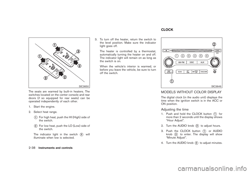
The seats are warmed by built-in heaters. The
switches located on the center console and rear
doors (if so equipped for rear seats) can be
operated independently of each other.
1. Start the engine.
2. Select heat range.
*1For high heat, push the HI (High) side of
the switch.
*2For low heat, push the LO (Low) side of
the switch.
The indicator light in the switch
*3will
illuminate when low is selected.3. To turn off the heater, return the switch to
the level position. Make sure the indicator
light goes off.
The heater is controlled by a thermostat,
automatically turning the heater on and off.
The indicator light will remain on as long as
the switch is on.
When the vehicle’s interior is warmed, or
before you leave the vehicle, be sure to turn
off the switch.
SIC3649
MODELS WITHOUT COLOR DISPLAY
The digital clock (in the audio unit) displays the
time when the ignition switch is in the ACC or
ON position.
Adjusting the time
1. Push and hold the CLOCK button*1for
more than 2 seconds until the display shows
“Hour Adjust”.
2. Turn the AUDIO knob
*2to adjust hours.
3. Push the CLOCK button
*1or AUDIO
knob
*2to enter. The display will show
“Minute Adjust”.
4. Turn the AUDIO knob
*2to adjust minutes.
CLOCK
2-38Instruments and controls
Page 119 of 443
Black plate (117,1)
Model "Z51-D" EDITED: 2007/ 10/ 2
SIC3505
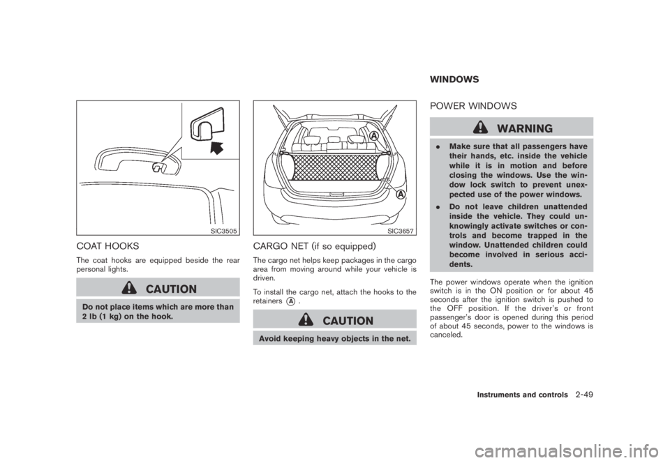
COAT HOOKS
The coat hooks are equipped beside the rear
personal lights.
CAUTION
Do not place items which are more than
2 lb (1 kg) on the hook.
SIC3657
CARGO NET (if so equipped)
The cargo net helps keep packages in the cargo
area from moving around while your vehicle is
driven.
To install the cargo net, attach the hooks to the
retainers
*A.
CAUTION
Avoid keeping heavy objects in the net.
POWER WINDOWS
WARNING
.Make sure that all passengers have
their hands, etc. inside the vehicle
while it is in motion and before
closing the windows. Use the win-
dow lock switch to prevent unex-
pected use of the power windows.
.Do not leave children unattended
inside the vehicle. They could un-
knowingly activate switches or con-
trols and become trapped in the
window. Unattended children could
become involved in serious acci-
dents.
The power windows operate when the ignition
switch is in the ON position or for about 45
seconds after the ignition switch is pushed to
the OFF position. If the driver’s or front
passenger’s door is opened during this period
of about 45 seconds, power to the windows is
canceled.
WINDOWS
Instruments and controls2-49
Page 124 of 443
Black plate (122,1)
Model "Z51-D" EDITED: 2007/ 10/ 2
SIC3249
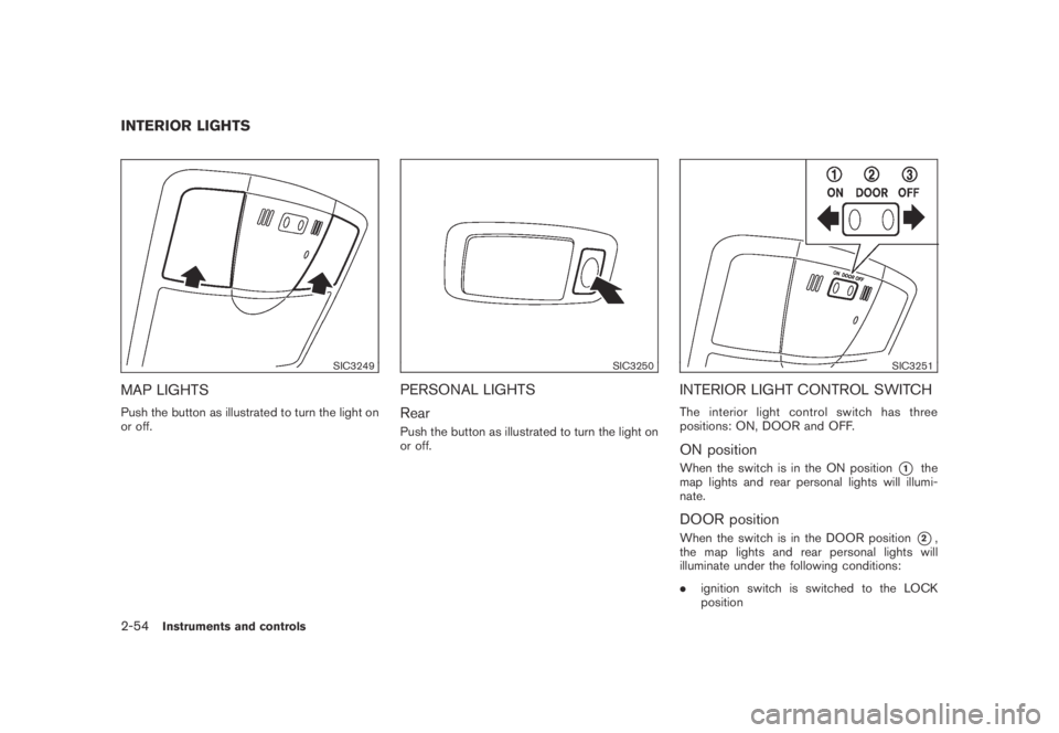
MAP LIGHTS
Push the button as illustrated to turn the light on
or off.
SIC3250
PERSONAL LIGHTS
Rear
Push the button as illustrated to turn the light on
or off.
SIC3251
INTERIOR LIGHT CONTROL SWITCH
The interior light control switch has three
positions: ON, DOOR and OFF.
ON position
When the switch is in the ON position*1the
map lights and rear personal lights will illumi-
nate.
DOOR position
When the switch is in the DOOR position*2,
the map lights and rear personal lights will
illuminate under the following conditions:
.ignition switch is switched to the LOCK
position
INTERIOR LIGHTS
2-54Instruments and controls
Page 125 of 443
Black plate (123,1)
Model "Z51-D" EDITED: 2007/ 10/ 2
— remain on for about 15 seconds.
.doors are unlocked by pushing the UN-
LOCK button on the Intelligent Key or door
handle request switch with the ignition
switch in the LOCK position
— remain on for about 15 seconds.
.any door is opened and then closed with the
ignition switch in the LOCK position
— remain on for about 15 seconds.
.any door is opened with the ignition switch
in the ACC or ON position
— remain on while the door is opened.
When the door is closed, the lights go off.
The lights will also turn off after 30
minutes when the lights remain illumi-
nated after the ignition switch has been
pushed to the OFF or LOCK position to
prevent the battery from becoming dis-
charged.
When the auto interior illumination is set to the
OFF position (see “VEHICLE INFORMATION
AND SETTINGS” in the “4. Monitor, heater, air
conditioner, audio, phone and voice recognition
systems” section) , the lights will illuminate under
the following condition:
.any door is opened with the ignition switch
in any position— remain on while the door is opened.
When the door is closed, the lights go off.
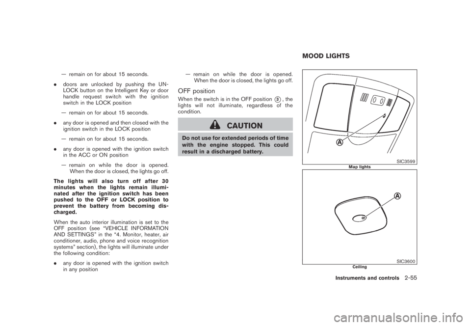
OFF position
When the switch is in the OFF position*3, the
lights will not illuminate, regardless of the
condition.
CAUTION
Do not use for extended periods of time
with the engine stopped. This could
result in a discharged battery.
SIC3599Map lights
SIC3600Ceiling
MOOD LIGHTS
Instruments and controls2-55
Page 127 of 443
Black plate (125,1)
Model "Z51-D" EDITED: 2007/ 10/ 2
HomeLink®Universal Transceiver provides a
convenient way to consolidate the functions of
up to three individual hand-held transmitters into
one built-in device.
HomeLink
®Universal Transceiver:
.Will operate most Radio Frequency (RF)
devices such as garage doors, gates, home
and office lighting, entry door locks and
security systems.
.Is powered by your vehicle’s battery. No
separate batteries are required. If the
vehicle’s battery is discharged or is dis-
connected, HomeLink
®will retain all pro-
gramming.
Once HomeLink
®Universal Transceiver is
programmed, retain the original transmit-
ter for future programming procedures
(Example: new vehicle purchases) . Upon
sale of the vehicle, the programmed
HomeLink
®Universal Transceiver buttons
should be erased for security purposes.
For additional information, see “PRO-
GRAMMING HomeLink
®” later in this sec-
tion.
WARNING
.Do not use HomeLink®Universal
Transceiver with any garage door
opener that lacks safety stop andreverse features as required by
federal safety standards. (These
standards became effective for
opener models manufactured after
April 1, 1982.) A garage door opener
which cannot detect an object in the
path of a closing garage door and
then automatically stop and reverse,
does not meet current federal safety
standards. Using a garage door
opener without these features in-
creases the risk of serious injury or
death.
.During programming procedure,
your garage door or security gate
may open or close. Make sure that
people and objects are clear of the
garage door, gate, etc. that you are
programming.
.Your vehicle’s engine should be
turned off while programming
HomeLink
®Universal Transceiver.
PROGRAMMING HomeLink®
To program your HomeLink®Transceiver to
operate a garage door, gate, or entry door
opener, home or office lighting, you need to be
at the same location as the device. Note:
Garage door openers (manufactured after1996) have “rolling code protection”. To pro-
gram a garage door opener equipped with
“rolling code protection”; you will need to use
a ladder to get up to the garage door opener
motor to be able to access the “smart or learn”
program button.
HomeLink®UNIVERSAL
TRANSCEIVER (if so equipped)
Instruments and controls2-57
Page 131 of 443

Black plate (10,1)
3 Pre-driving checks and adjustments
Model "Z51-D" EDITED: 2007/ 10/ 2
Keys ............................................................... 3-2
NISSAN Vehicle Immobilizer System keys............ 3-2
Intelligent Key system (if so equipped)................ 3-3
Mechanical key.............................................. 3-4
Valet hand-off................................................ 3-4
Doors.............................................................. 3-4
Locking with mechanical key............................. 3-5
Opening and closing windows with the
mechanical key.............................................. 3-5
Locking with inside lock knob........................... 3-5
Locking with power door lock switch.................. 3-6
Vehicle speed sensing door lock mechanism........ 3-6
Automatic door unlock mechanism..................... 3-6
Child safety rear door lock............................... 3-7
Intelligent Key system (if so equipped).................... 3-7
Intelligent Key operating range.......................... 3-8
Door locks/unlocks precaution.......................... 3-9
Intelligent Key operation.................................3-10
Battery saver system.....................................3-13
Warning signals...........................................3-13
Troubleshooting guide...................................3-14
Remote keyless entry system..............................3-15
How to use remote keyless entry system...........3-15Hood............................................................3-18
Lift gate.........................................................3-18
Operating manual lift gate..............................3-19
Operating power lift gate (if so equipped)..........3-19
Auto closure...............................................3-22
Lift gate release...........................................3-23
Fuel-filler door.................................................3-23
Opening fuel-filler door..................................3-23
Fuel-filler cap..............................................3-23
Tilting telescopic steering column........................3-25
Manual operation.........................................3-25
Electric operation.........................................3-25
Sun visors......................................................3-26
Mirrors...........................................................3-27
Inside mirror................................................3-27
Outside mirrors............................................3-28
Vanity mirror................................................3-29
Automatic drive positioner (if so equipped).............3-30
Entry/exit function.........................................3-30
Memory storage...........................................3-30
System operation.........................................3-31