2009 NISSAN LATIO hood open
[x] Cancel search: hood openPage 2747 of 4331
EC
NP
O
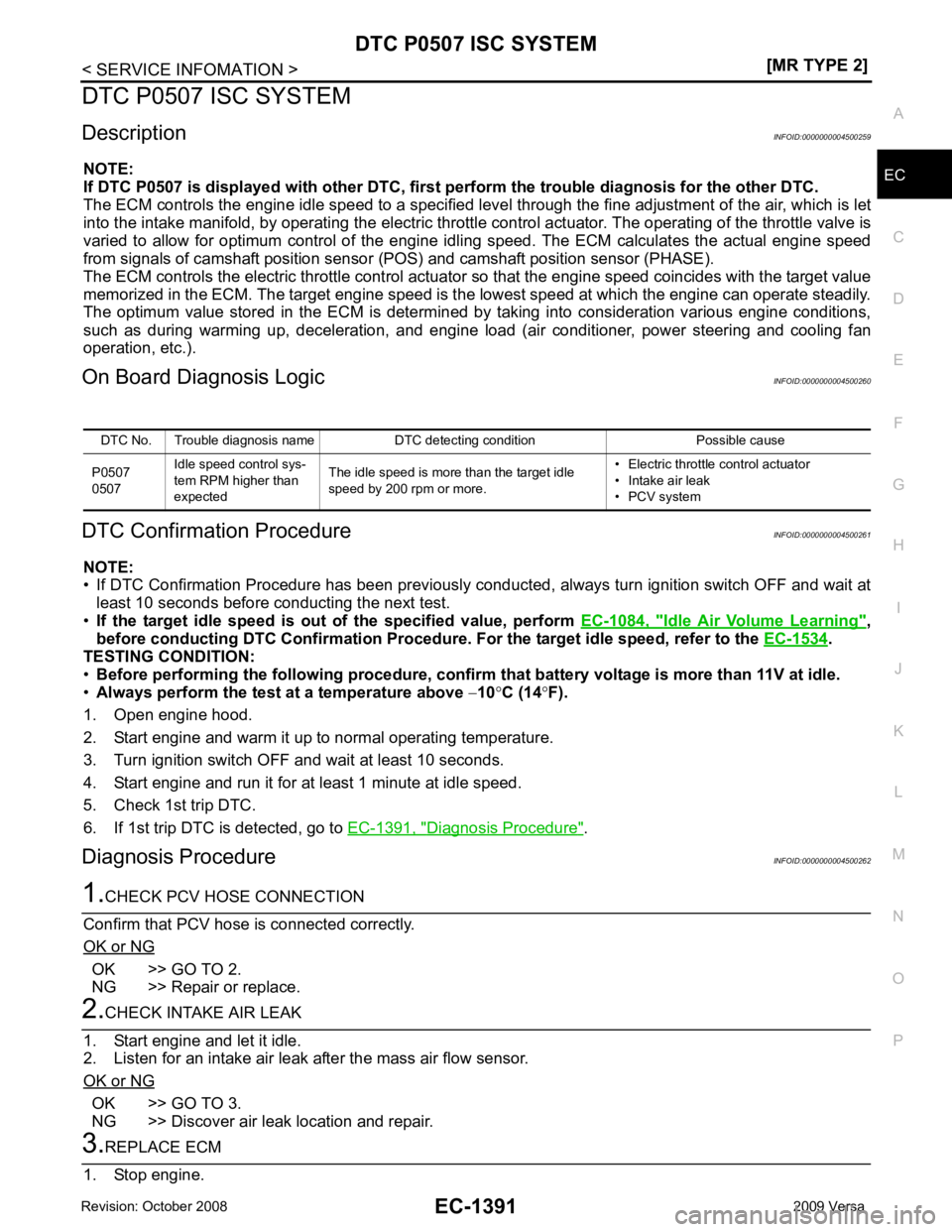
DTC P0507 ISC SYSTEM
Description INFOID:0000000004500259
NOTE:
If DTC P0507 is displayed with ot her DTC, first perform the trouble diagnosis for the other DTC.
The ECM controls the engine idle speed to a specified leve l through the fine adjustment of the air, which is let
into the intake manifold, by operating the electric thrott le control actuator. The operating of the throttle valve is
varied to allow for optimum control of the engine id ling speed. The ECM calculates the actual engine speed
from signals of camshaft position sensor (POS) and camshaft position sensor (PHASE).
The ECM controls the electric throttle control actuator so that the engine speed coincides with the target value
memorized in the ECM. The target engine speed is t he lowest speed at which the engine can operate steadily.
The optimum value stored in the ECM is determined by taking into consideration various engine conditions,
such as during warming up, deceleration, and engine load (air conditioner, power steering and cooling fan
operation, etc.).
On Board Diagnosis Logic INFOID:0000000004500260
DTC Confirmation Procedure INFOID:0000000004500261
NOTE:
• If DTC Confirmation Procedure has been previously conduc ted, always turn ignition switch OFF and wait at
least 10 seconds before conducting the next test.
• If the target idle speed is out of the specified value, perform EC-1084, " Idle Air Volume Learning " ,
before conducting DTC Confirmation Procedure. For the target idle speed, refer to the EC-1534 .
TESTING CONDITION:
• Before performing the following procedure, confirm that battery voltage is more than 11V at idle.
• Always perform the test at a temperature above −10 °C (14 °F).
1. Open engine hood.
2. Start engine and warm it up to normal operating temperature.
3. Turn ignition switch OFF and wait at least 10 seconds.
4. Start engine and run it for at least 1 minute at idle speed.
5. Check 1st trip DTC.
6. If 1st trip DTC is detected, go to EC-1391, " Diagnosis Procedure " .
Diagnosis Procedure INFOID:0000000004500262OK >> GO TO 2.
NG >> Repair or replace. OK >> GO TO 3.
NG >> Discover air leak location and repair.
Page 2912 of 4331
EI
N
O P
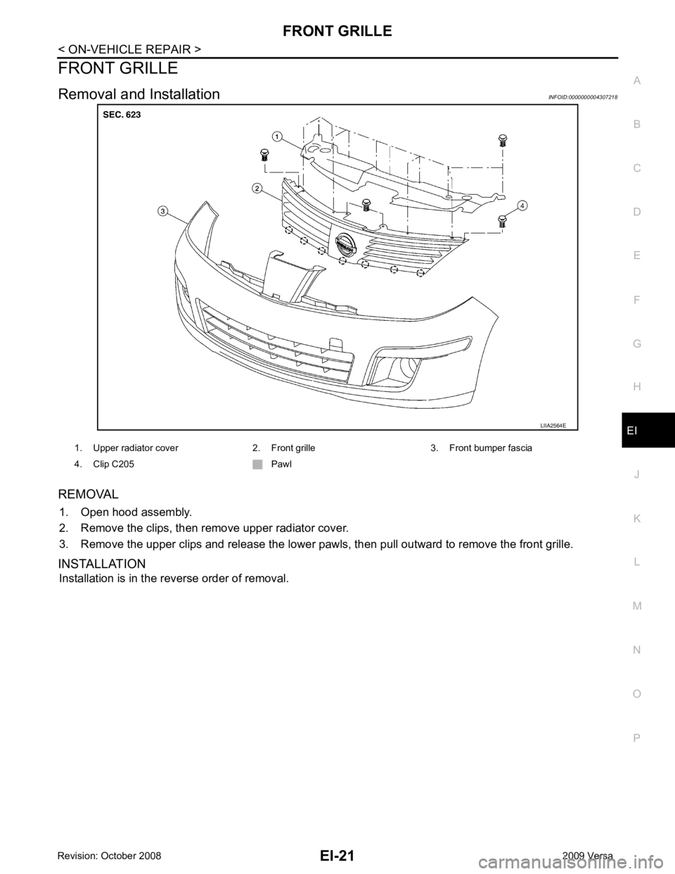
FRONT GRILLE
Removal and Installation INFOID:0000000004307218
REMOVAL 1. Open hood assembly.
2. Remove the clips, then remove upper radiator cover.
3. Remove the upper clips and release the lower pawls, then pull outward to remove the front grille.
INSTALLATION Installation is in the reverse order of removal.
Page 3386 of 4331
.
22. Remove wiper & washer switch. Refer to WW-23, " Removal and Installation of Front Wiper and Washer
Switch " .
23. Remove hood opener handle and fuel filler lid opener handle. Refer to BL-15, " Removal and Installation of
Hood Lock Control " .
24. Remove screws, and then remove instrument panel & pad from passenger door opening portion.
Installation
Installation is in the reverse order of removal.
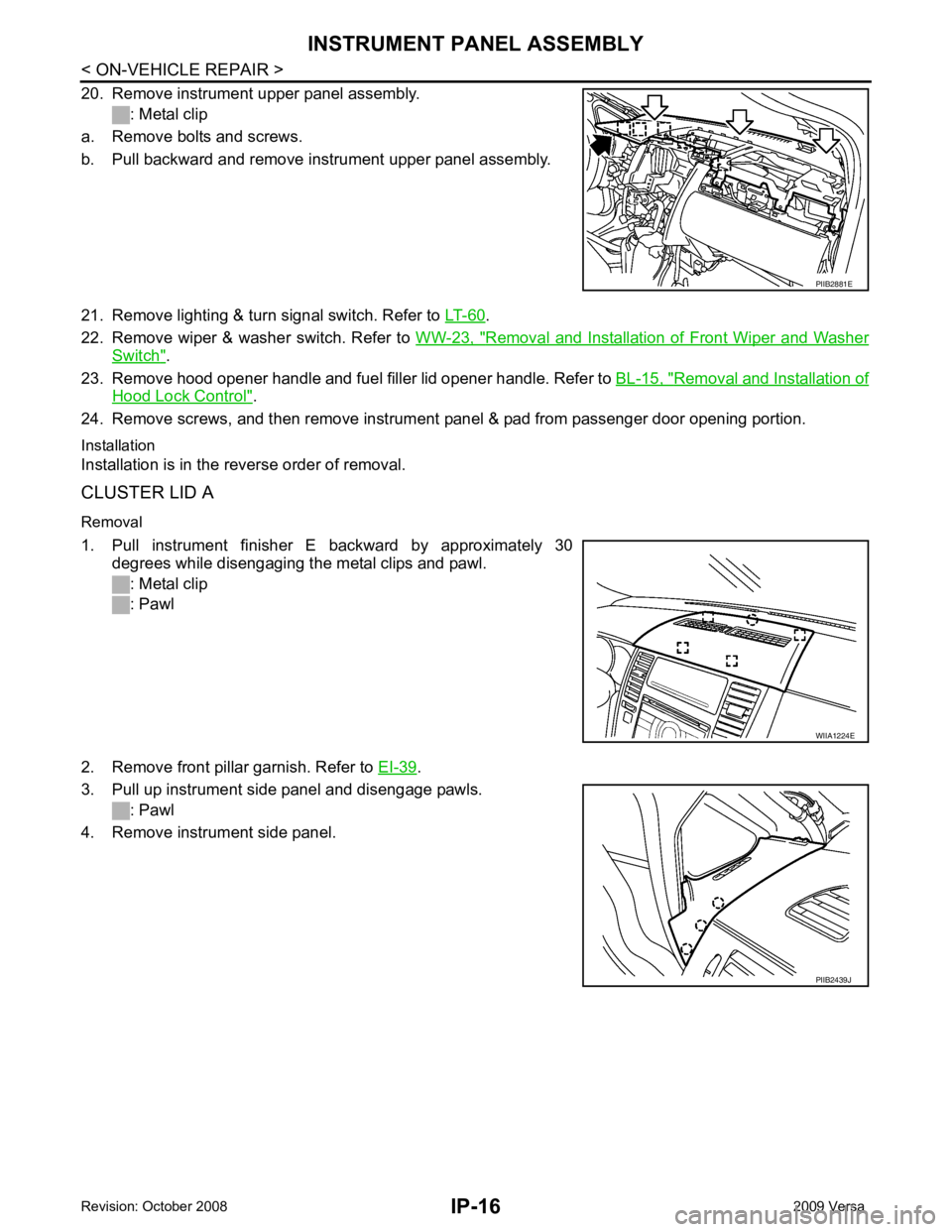
CLUSTER LID A
Removal
1. Pull instrument finisher E backward by approximately 30 degrees while disengaging the metal clips and pawl.
: Metal clip
: Pawl
2. Remove front pillar garnish. Refer to EI-39 .
3. Pull up instrument side panel and disengage pawls. : Pawl
4. Remove instrument side panel. WIIA1224E
PIIB2439J
Page 3934 of 4331

MTC
N
O P
Testing must be performed as follows:
TEST READING Recirculating-to-discharge Air Temperature Table
Ambient Air Temperature-to-operating Pressure Table
*1: With blower control dial in the "1" position
*2: With blower control dial in the "4" position.
TROUBLE DIAGNOSIS FOR ABNORMAL PRESSURE Whenever system’s high and/or low side pressure(s) is /are abnormal, diagnose using a manifold gauge. The
marker above the gauge scale in the following tables indicates the standard (usual) pressure range. Since the
standard (usual) pressure, however, differs from vehicle to vehicle, refer to above table (Ambient air tempera-
ture-to-operating pressure table). Vehicle condition Indoors or in the shade (in a well-ventilated place)
Doors Closed
Door window Open
Hood Open
TEMP. Max. COLD
Mode control dial (Ventilation) set
Intake door lever (Recirculation) set
Blower speed Max. speed set
Engine speed Idle speed
Operate the air conditioning system for 10 minutes before taking measurements. Inside air (Recirculating air) at blower assembly inlet
Discharge air temperature at center ventilator
°C ( °F)
Relative humidity
% Air temperature
°C ( °F)
50 - 60 20 (68) 7.2 - 9.1 (45 - 48)
25 (77) 11.4 - 13.8 (53 - 57)
30 (86) 15.5 - 18.4 (60 - 65)
35 (95) 20.3 - 23.7 (69 - 75)
60 - 70 20 (68) 9.1 - 10.9 (48 - 52)
25 (77) 13.8 - 16.2 (57 - 61)
30 (86) 18.4 - 21.3 (65 - 70)
35 (95) 23.7 - 27.1 (75 - 81) Ambient air
High-pressure (Discharge side)
kPa (bar, kg/cm 2
, psi) Low-pressure (Suction side)
kPa (bar, kg/cm 2
, psi)
Relative humidity
% Air temperature
°C ( °F)
50 - 70 20 (68)
843 - 1,036 *1
(11.08 - 13.63, 8.6 - 10.6, 122 - 150) 159.0 - 194.0
(1.59 - 1.94, 1.62 - 1.98, 23.1 - 28.1)
25 (77) 1,094 - 1,338 *1
(10.94 - 13.38, 11.2 - 13.6, 159 - 194) 196.3 - 240.0
(1.96 - 2.40, 2.00 - 2.45, 28.5 - 34.8)
30 (86) 1,298 - 1,590 *1
(12.98 - 15.90, 13.2 - 16.2, 188 - 231) 248.0 - 302.7
(2.48 - 3.03, 2.53 - 3.09, 36.0 - 43.9)
35 (95) 1,383 - 1,688 *2
(13.83 - 16.88, 14.1 - 17.2, 201 - 245) 308.8 - 377.4
(3.09 - 3.77, 3.15 - 3.85, 44.8 - 54.7)
40 (104) 1,628 - 1,988 *2
(16.28 - 19.88, 16.6 - 20.3, 236 - 288) 377.4 - 461.2
(3.77 - 4.61, 3.85 - 4.70, 54.7 - 66.8)
Page 4001 of 4331

Item name
CONSULT-III
screen display Display or unit Monitor item selection
Description
ALL
SIGNALS MAIN
SIGNALS SELECTION
FROM MENU
Motor fan request MOTOR FAN
REQ 1/2/3/4 X X X Signal status input from ECM
Compressor re-
quest AC COMP REQ ON/OFF X X X Signal status input from ECM
Parking, license,
and tail lamp re-
quest TAIL & CLR REQ ON/OFF X X X Signal status input from BCM
Headlamp low
beam request HL LO REQ ON/OFF X X X Signal status input from BCM
Headlamp high
beam request HL HI REQ ON/OFF X X X Signal
status input from BCM
Front fog request FR FOG REQ ON/OFF X X X Signal status input from BCM
FR wiper request FR WIP REQ STOP/1LO/LO/HI X X X Signal status input from BCM
Wiper auto stop WIP AUTO
STOP ACT P/STOP P X X X Output status of IPDM E/R
Wiper protection WIP PROT OFF/LS/HS/Block X X X Control status of IPDM E/R
Starter request ST RLY REQ ON/OFF X X Status of input signal (*1)
Ignition relay
status IGN RLY ON/OFF X X X Ignition relay status monitored
with IPDM E/R
Rear defogger re-
quest RR DEF REQ ON/OFF X X X Signal status input from BCM
Oil pressure
switch OIL P SW OPEN/CLOSE X X
Signal status input from IPDM
E/R
Hood switch HOOD SW (*2) OFF X X Signal status input from IPDM
E/R
Page 4002 of 4331
PG
N
O P
*1 Perform monitoring of IPDM E/R data with the ignition switch ON. When the ignition switch is in ACC position, display may no
t be cor-
rect.
*2 This item is displayed, but does not function.
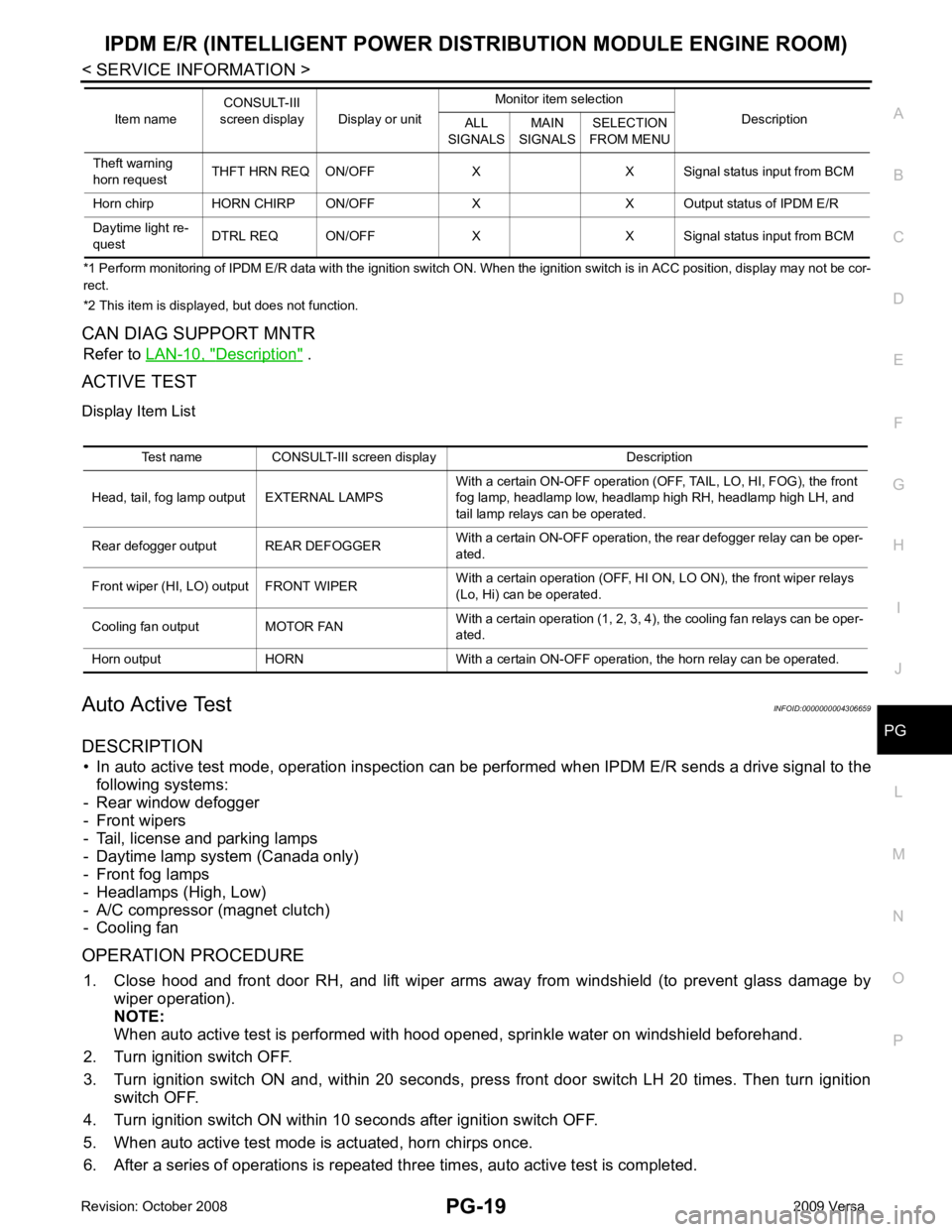
CAN DIAG SUPPORT MNTR Refer to LAN-10, " Description " .
ACTIVE TEST
Display Item List
Auto Active Test INFOID:0000000004306659
DESCRIPTION • In auto active test mode, operation inspection can be performed when IPDM E/R sends a drive signal to the
following systems:
- Rear window defogger
- Front wipers
- Tail, license and parking lamps
- Daytime lamp system (Canada only)
- Front fog lamps
- Headlamps (High, Low)
- A/C compressor (magnet clutch)
- Cooling fan
OPERATION PROCEDURE 1. Close hood and front door RH, and lift wiper arms away from windshield (to prevent glass damage by
wiper operation).
NOTE:
When auto active test is performed with hood opened, sprinkle water on windshield beforehand.
2. Turn ignition switch OFF.
3. Turn ignition switch ON and, within 20 seconds, pre ss front door switch LH 20 times. Then turn ignition
switch OFF.
4. Turn ignition switch ON within 10 seconds after ignition switch OFF.
5. When auto active test mode is actuated, horn chirps once.
6. After a series of operations is repeated th ree times, auto active test is completed.
Theft warning
horn request THFT HRN REQ ON/OFF X X Signal status input from BCM
Horn chirp HORN CHIRP ON/OFF X X O utput status of IPDM E/R
Daytime light re-
quest DTRL REQ ON/OFF X X Signal
status input from BCM
Item name
CONSULT-III
screen display Display or unit Monitor item selection
Description
ALL
SIGNALS MAIN
SIGNALS SELECTION
FROM MENU Test name CONSULT-III screen display Description
Head, tail, fog lamp output EXTERNAL LAMPS With a certain ON-OFF operation (OFF, TAIL, LO, HI, FOG), the front
fog lamp, headlamp low, headlamp high RH, headlamp high LH, and
tail lamp relays can be operated.
Rear defogger output REAR DEFOGGER With a certain ON-OFF operation, the rear defogger relay can be oper-
ated.
Front wiper (HI, LO) output FRONT WIPER With a certain operation (OFF, HI ON, LO ON), the front wiper relays
(Lo, Hi) can be operated.
Cooling fan output MOTOR FAN With a certain operation (1, 2, 3, 4), the cooling fan relays can be oper-
ated.
Horn output HORN With a certain ON-OFF operation, the horn relay can be operated.
Page 4310 of 4331
Combination Switch Inspection " .
OK or NG OK >> Replace BCM. Refer to
BCS-18, " Removal and Installation of BCM " .
NG >> Check combination switch (wiper switch). Refer to LT-63, " Combination Switch Inspection " .
Front Wiper Intermittent Operation S witch Position Cannot Be Adjusted INFOID:0000000004306920Combination Switch Inspection " .
OK or NG OK >> Replace BCM. Refer to
BCS-18, " Removal and Installation of BCM " .
NG >> Check combination switch (wiper switch). Refer to LT-63, " Combination Switch Inspection " .
Wiper Does Not Wipe Wh en Front Washer Operates INFOID:0000000004306921Combination Switch Inspection " .
OK or NG OK >> Replace BCM. Refer to
BCS-18, " Removal and Installation of BCM " .
NG >> Check combination switch (wiper switch). Refer to LT-63, " Combination Switch Inspection " .
Front Wiper Does Not Stop INFOID:0000000004306922Combination Switch Inspection " .
OK or NG OK >> Replace IPDM E/R. Refer to
PG-26, " IPDM E/R Power/Ground Circuit Inspection " .
NG >> Check combination switch (wiper switch). Refer to LT-63, " Combination Switch Inspection " .
Removal and Installation of Front Wiper Arms INFOID:0000000004306923
REMOVAL
1. Turn wiper switch on to operate wiper motor, and then turn wiper switch off (auto stop).
2. Open hood, remove wiper arm caps, and remove wiper arm nuts.
3. Raise wiper arm, and remove wiper arm from the vehicle.
INSTALLATION