2009 NISSAN LATIO brake sensor
[x] Cancel search: brake sensorPage 8 of 4331

AT
N
O
P
N
Wiring Diagram - AT -
SSV/B ................................
145
Diagnosis Procedure ........................................... ..146
Component Inspection ........................................ ..147
DTC P1760 OVERRUN CLUTCH SOLENOID
VALVE ............................................................ ..149
Description .......................................................... ..149
CONSULT-III Refe rence Value in Data Monitor
Mode ................................................................... ..
149
On Board Diagnosis Logic .................................. ..149
Possible Cause ................................................... ..149
DTC Confirmation Procedure .............................. ..149
Wiring Diagram - AT - OVRCSV ......................... ..150
Diagnosis Procedure ........................................... ..151
Component Inspection ........................................ ..152
DTC VEHICLE SPEED SENSOR MTR .......... ..154
Description .......................................................... ..154
CONSULT-III Refe rence Value in Data Monitor
Mode ................................................................... ..
154
On Board Diagnosis Logic .................................. ..154
Possible Cause ................................................... ..154
DTC Confirmation Procedure .............................. ..154
Wiring Diagram - AT - VSSMTR ...........................155
Diagnosis Procedure ........................................... ..156
DTC BATT/FLUID TEMP SEN (A/T FLUID
TEMP SENSOR CIRCUIT AND TCM POWER
SOURCE) ....................................................... ..
157
Description .......................................................... ..157
CONSULT-III Refe rence Value in Data Monitor
Mode ................................................................... ..
157
On Board Diagnosis Logic .................................. ..157
Possible Cause ................................................... ..157
DTC Confirmation Procedure .............................. ..157
Wiring Diagram - AT - BA/FTS ............................ ..158
Diagnosis Procedure ........................................... ..159
Component Inspection ........................................ ..161
DTC TURBINE REVOLUTION SENSOR ....... ..163
Description .......................................................... ..163
CONSULT-III Refe rence Value in Data Monitor
Mode ................................................................... ..
163
On Board Diagnosis Logic .................................. ..163
Possible Cause ................................................... ..163
DTC Confirmation Procedure .............................. ..163
Wiring Diagram - AT - PT/SEN ........................... ..164
Diagnosis Procedure ........................................... ..165
CONTROL UNIT (RAM), CONTROL UNIT
(ROM) ............................................................. ..
168
Description .......................................................... ..168
On Board Diagnosis Logic .................................. ..168
Possible Cause ................................................... ..168
DTC Confirmation Procedure .............................. ..168
Diagnosis Procedure ........................................... ..168
MAIN POWER SUPPLY AND GROUND CIR-
CUIT ................................................................ ..169
Wiring Diagram - AT - MAIN ............................... ..169 Diagnosis Procedure ...........................................
..170
PNP, OD SWITCH AND CLOSED THROT-
TLE, WIDE OPEN THROTTLE POSITION
SIGNAL CIRCUI T ............................................ 172
CONSULT-III Reference Va lue in Data Monitor
Mode .................................................................... ..
172
TCM Terminal and Refere nce Value .....................172
Diagnosis Procedure ........................................... ..172
Component Inspection ......................................... ..176
SHIFT POSITION INDICATOR CIRCUIT ........ 177
Description ........................................................... ..177
CONSULT-III Reference Va lue in Data Monitor
Mode .................................................................... ..
177
Diagnosis Procedure ........................................... ..177
TROUBLE DIAGNOSIS FOR SYMPTOMS .... 178
Wiring Diagram - AT - NONDTC ......................... ..178
OD OFF Indicator Lamp Does Not Come On ...... ..181
Engine Cannot Be Started in "P" and "N" Position ..183
In "P" Position, Vehicle Moves Forward or Back-
ward When Pushed ............................................. ..
184
In "N" Position, Vehicle Moves ............................ ..184
Large Shock "N" → "R" Position .......................... ..185
Vehicle Does Not Creep Backward in "R" Position ..186
Vehicle Does Not Creep Forw ard in "D", "2" or "1"
Position ................................................................ ..
187
Vehicle Cannot Be Started from D 1 ..................... ..188
A/T Does Not Shift: D 1→ D 2or Does Not Kick-
down: D 4→ D 2 ..................................................... ..190
A/T Does Not Shift: D 2→ D 3 ................................ ..192
A/T Does Not Shift: D 3→ D 4 ................................ ..193
A/T Does Not Perform Lock-up ........................... ..194
A/T Does Not Hold Lock-up Condition ................. ..195
Lock-up Is Not Released ..................................... ..196
Engine Speed Does Not Return to Idle (Light
Braking D 4→ D 3) ................................................. ..197
A/T Does Not Shift: D 4→ D 3, When OD OFF ...... ..198
A/T Does Not Shift: D 3→ 22, When Selector Lever
"D" → "2" Position ............................................... ..
199
A/T Does Not Shift: 2 2→ 11, When Selector Lever
"2" → "1" Position ................................................ ..
200
Vehicle Does Not Decelerate by Engine Brake ... ..202
TCM Self-Diagnosis Does Not Activate ............... ..205
A/T SHIFT LOCK SYSTEM ............................. 207
Description ........................................................... ..207
Shift Lock System Parts Location ........................ ..207
Wiring Diagram - AT - SHIFT .............................. ..208
Diagnosis Procedure ........................................... ..208
TRANSMISSION CONTROL MODULE .......... 211
Removal and Installation ..................................... ..211
SHIFT CONTROL SYSTEM ............................ 212
Control Device Removal an d Installation ...............212
Control Device Disassembly and Assembly ..........215
Selector Lever Knob Remo val and Installation ......215
Adjustment of A/T Position .................................. ..216
Page 38 of 4331
AT
N
O P
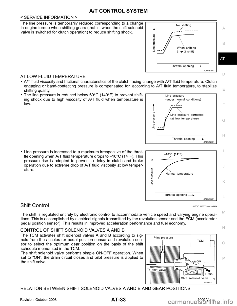
The line pressure is temporarily reduced corresponding to a change
in engine torque when shifting gears (that is, when the shift solenoid
valve is switched for clutch operation) to reduce shifting shock.
AT LOW FLUID TEMPERATURE • A/T fluid viscosity and frictional characteristics of t he clutch facing change with A/T fluid temperature. Clutch
engaging or band-contacting pressure is compensated for, according to A/T fluid temperature, to stabilize
shifting quality.
• The line pressure is reduced below 60 °C (140 °F) to prevent shift-
ing shock due to high viscosity of A/T fluid when temperature is
low.
• Line pressure is increased to a maximum irrespective of the throt- tle opening when A/T fluid temperature drops to −10 °C (14 °F). This
pressure rise is adopted to prevent a delay in clutch and brake
operation due to extreme drop of A/T fluid viscosity at low temper-
ature.
Shift Control INFOID:0000000004305304
The shift is regulated entirely by electronic cont rol to accommodate vehicle speed and varying engine opera-
tions. This is accomplished by electrical signals trans mitted by the revolution sensor and the ECM (accelerator
pedal position sensor). This results in improved acceleration performance and fuel economy.
CONTROL OF SHIFT SOLENOID VALVES A AND B The TCM activates shift solenoid valves A and B according to sig-
nals from the accelerator pedal position sensor and revolution sen-
sor to select the optimum gear pos ition on the basis of the shift
schedule memorized in the TCM.
The shift solenoid valve performs simple ON-OFF operation. When
set to “ON”, the drain circuit closes and pilot pressure is applied to
the shift valve.
RELATION BETWEEN SHIFT SOLENOID VALVES A AND B AND GEAR POSITIONS SAT008J
Page 48 of 4331
AT
N
O P
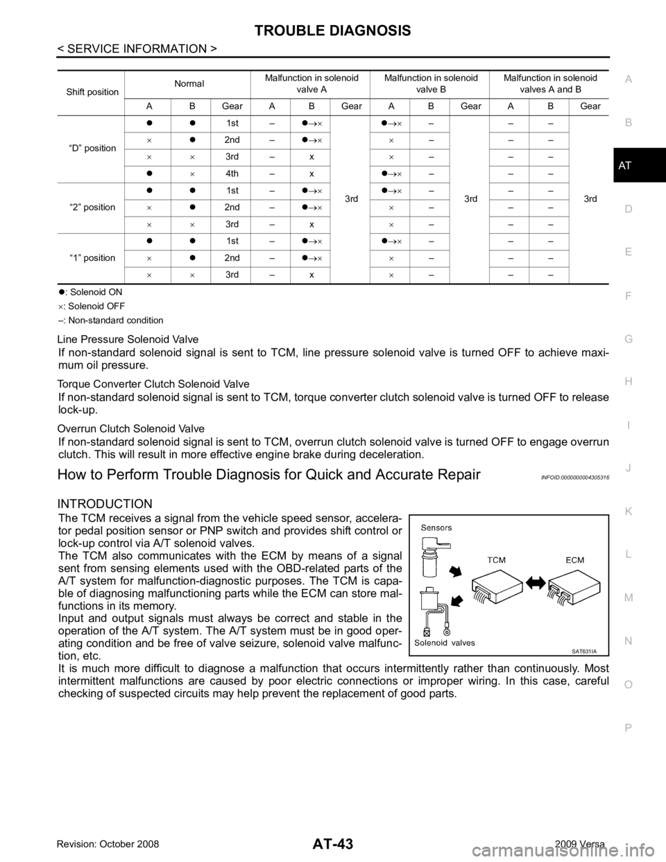
�z
: Solenoid ON
× : Solenoid OFF
–: Non-standard condition
Line Pressure Solenoid Valve If non-standard solenoid signal is sent to TCM, line pre ssure solenoid valve is turned OFF to achieve maxi-
mum oil pressure.
Torque Converter Clutch Solenoid Valve If non-standard solenoid signal is sent to TCM, torque conv erter clutch solenoid valve is turned OFF to release
lock-up.
Overrun Clutch Solenoid Valve If non-standard solenoid signal is sent to TCM, overr un clutch solenoid valve is turned OFF to engage overrun
clutch. This will result in more effective engine brake during deceleration.
How to Perform Trouble Diagnosis for Quick and Accurate Repair INFOID:0000000004305316
INTRODUCTION The TCM receives a signal from the vehicle speed sensor, accelera-
tor pedal position sensor or PNP switch and provides shift control or
lock-up control via A/T solenoid valves.
The TCM also communicates with the ECM by means of a signal
sent from sensing elements used wit h the OBD-related parts of the
A/T system for malfunction-diagnostic purposes. The TCM is capa-
ble of diagnosing malfunctioning parts while the ECM can store mal-
functions in its memory.
Input and output signals must always be correct and stable in the
operation of the A/T system. T he A/T system must be in good oper-
ating condition and be free of valve seizure, solenoid valve malfunc-
tion, etc.
It is much more difficult to diagnose a malfunction t hat occurs intermittently rather than continuously. Most
intermittent malfunctions are caused by poor electric c onnections or improper wiring. In this case, careful
checking of suspected circuits may hel p prevent the replacement of good parts.
Shift position
Normal
Malfunction in solenoid
valve A Malfunction in solenoid
valve B Malfunction in solenoid
valves A and B
A B Gear A B Gear A B Gear A B Gear
“D” position �z �z
1st –�z→×
3rd �z
→× –
3rd – –
3rd
×
�z2nd – �z→× × – – –
× × 3rd – x ×– – –
�z ×4th – x �z→× – – –
“2” position �z �z
1st –�z→× �z→× – – –
× �z2nd – �z→× × – – –
× × 3rd – x ×– – –
“1” position �z �z
1st –�z→× �z→× – – –
× �z2nd – �z→× × – – –
× × 3rd – x ×– – –
Page 53 of 4331
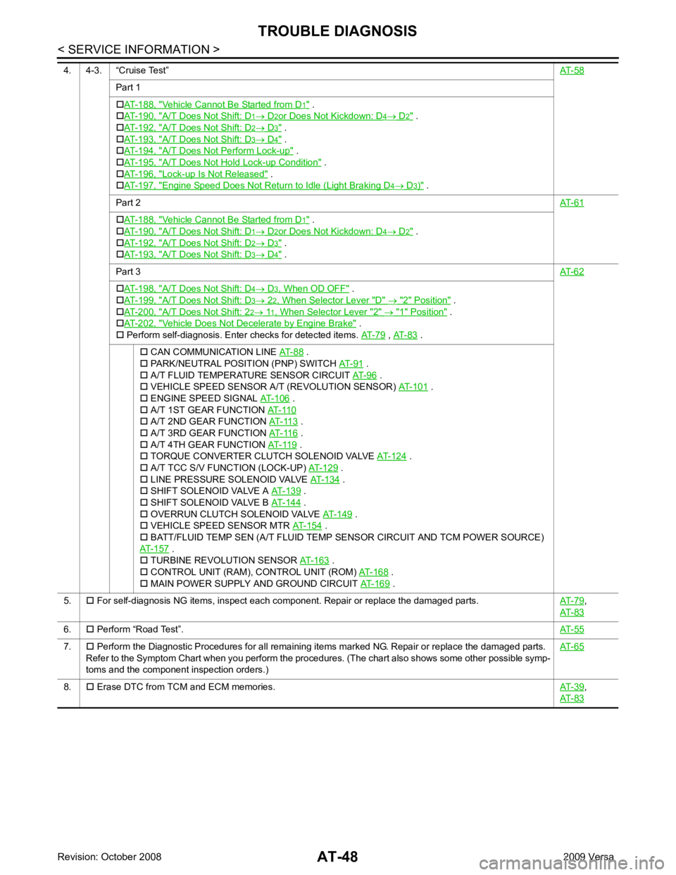
Part 1
�† AT-188, " Vehicle Cannot Be Started from D .
�† AT-190, " A/T Does Not Shift: D .
�† AT-192, " A/T Does Not Shift: D .
�† AT-193, " A/T Does Not Shift: D .
�† AT-194, " A/T Does Not Perform Lock-up " .
�† AT-195, " A/T Does Not Hold
Lock-up Condition " .
�† AT-196, " Lock-up Is Not Released " .
�† AT-197, " Engine Speed Does Not Return to Idle (Light Braking D " .
Part 2 AT-61Vehicle Cannot Be Started from D .
�† AT-190, " A/T Does Not Shift: D .
�† AT-192, " A/T Does Not Shift: D .
�† AT-193, " A/T Does Not Shift: D .
Part 3 AT-62A/T Does Not Shift: D " .
�† AT-199, " A/T Does Not Shift: D " .
�† AT-200, " A/T Does Not Shift: 2 " .
�† AT-202, " Vehicle Does Not Decelerate by Engine Brake " .
�† Perform self-diagnosis. Enter checks for detected items. AT-79 ,
AT-83 .
�† CAN COMMUNICATION LINE AT-88 .
�† PARK/NEUTRAL POSITION (PNP) SWITCH AT-91 .
�† A/T FLUID TEMPERATURE SENSOR CIRCUIT AT-96 .
�† VEHICLE SPEED SENSOR A/T (REVOLUTION SENSOR) AT-101 .
�† ENGINE SPEED SIGNAL AT-106 .
�† A/T 1ST GEAR FUNCTION AT-110 .
�† A/T 3RD GEAR FUNCTION AT-116 .
�† A/T 4TH GEAR FUNCTION AT-119 .
�† TORQUE CONVERTER CLUTCH SOLENOID VALVE AT-124 .
�† A/T TCC S/V FUNCTION (LOCK-UP) AT-129 .
�† LINE PRESSURE SOLENOID VALVE AT-134 .
�† SHIFT SOLENOID VALVE A AT-139 .
�† SHIFT SOLENOID VALVE B AT-144 .
�† OVERRUN CLUTCH SOLENOID VALVE AT-149 .
�† VEHICLE SPEED SENSOR MTR AT-154 .
�† BATT/FLUID TEMP SEN (A/T FLUID TEMP SENSOR CIRCUIT AND TCM POWER SOURCE)
AT-157 .
�† TURBINE REVOLUTION SENSOR AT-163 .
�† CONTROL UNIT (RAM), CONTROL UNIT (ROM) AT-168 .
�† MAIN POWER SUPPLY AND GROUND CIRCUIT AT-169 .
5. �† For self-diagnosis NG items, inspect each component. Repair or replace the damaged parts. AT-79 ,
AT-83 6.
�† Perform “Road Test”. AT-557.
�† Perform the Diagnostic Procedures for all remaining items marked NG. Repair or replace the damaged parts.
Refer to the Symptom Chart when you perform the procedures. (The chart also shows some other possible symp-
toms and the component inspection orders.) AT-658.
�† Erase DTC from TCM and ECM memories. AT-39 ,
AT-83
Page 60 of 4331
AT
N
O P
Line Pressure
Judgement of Line Pressure Test
Road Test INFOID:0000000004305320
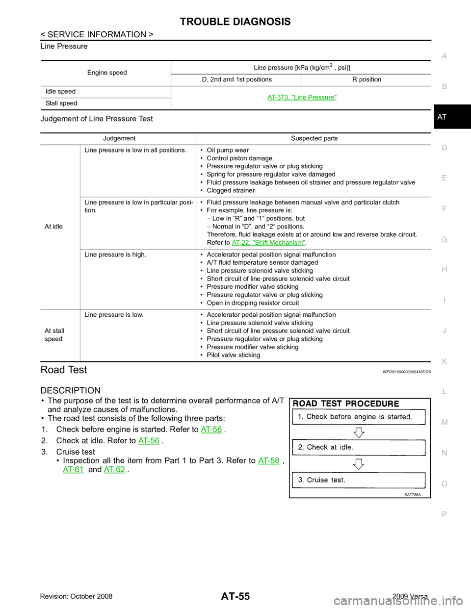
DESCRIPTION • The purpose of the test is to det ermine overall performance of A/T
and analyze causes of malfunctions.
• The road test consists of the following three parts:
1. Check before engine is started. Refer to AT-56 .
2. Check at idle. Refer to AT-56 .
3. Cruise test • Inspection all the item from Part 1 to Part 3. Refer to AT-58 ,
AT-61 and
AT-62 .
Engine speed
Line pressure [kPa (kg/cm
2
, psi)]
D, 2nd and 1st positions R position
Idle speed AT-373, " Line Pressure "
Stall speed
Judgement Suspected parts
At idle Line pressure is low in all positions. • Oil pump wear
• Control piston damage
• Pressure regulator valve or plug sticking
• Spring for pressure regulator valve damaged
• Fluid pressure leakage between oil strainer and pressure regulator valve
• Clogged strainer
Line pressure is low in particular posi-
tion. • Fluid pressure leakage between manual valve and particular clutch
• For example, line pressure is: − Low in “R” and “1 ” positions, but
− Normal in “D”, and “2” positions.
Therefore, fluid leakage exists at or around low and reverse brake circuit.
Refer to AT-22, " Shift Mechanism " .
Line pressure is high. • Accelerator pedal position signal malfunction • A/T fluid temperature sensor damaged
• Line pressure solenoid valve sticking
• Short circuit of line pressure solenoid valve circuit
• Pressure modifier valve sticking
• Pressure regulator valve or plug sticking
• Open in dropping resistor circuit
At stall
speed Line pressure is low. • Accelerator pedal position signal malfunction
• Line pressure solenoid valve sticking
• Short circuit of line pressure solenoid valve circuit
• Pressure regulator valve or plug sticking
• Pressure modifier valve sticking
• Pilot valve sticking
Page 71 of 4331
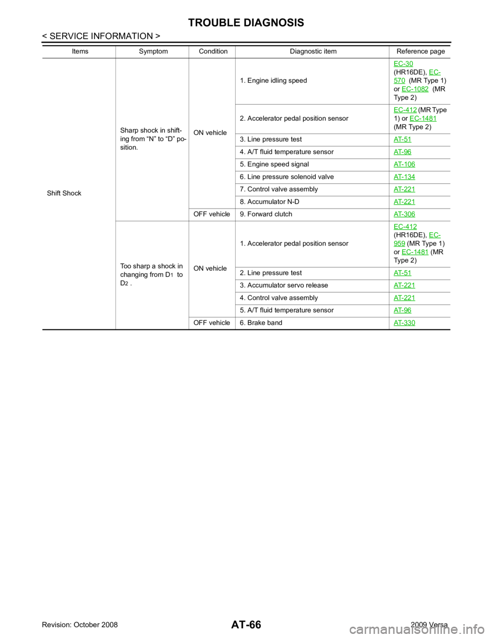
(HR16DE), EC- 570 (MR Type 1)
or EC-1082 (MR
Type 2)
2. Accelerator pedal position sensor EC-412 (MR Type
1) or EC-1481
(MR Type 2)
3. Line pressure test AT-51 4. A/T fluid temperature sensor
AT-96 5. Engine speed signal
AT-106 6. Line pressure solenoid valve
AT-134 7. Control valve assembly
AT-221 8. Accumulator N-D
AT-221 OFF vehicle 9. Forward clutch
AT-306Too sharp a shock in
changing from D 1 to
D 2 . ON vehicle1. Accelerator pedal position sensor
EC-412
(HR16DE), EC- 959 (MR Type 1)
or EC-1481 (MR
Type 2)
2. Line pressure test AT-51 3. Accumulator servo release
AT-221 4. Control valve assembly
AT-221 5. A/T fluid temperature sensor
AT-96 OFF vehicle 6. Brake band
AT-330Items Symptom Condition Diagnostic item Reference page
Page 72 of 4331
AT
N
O P
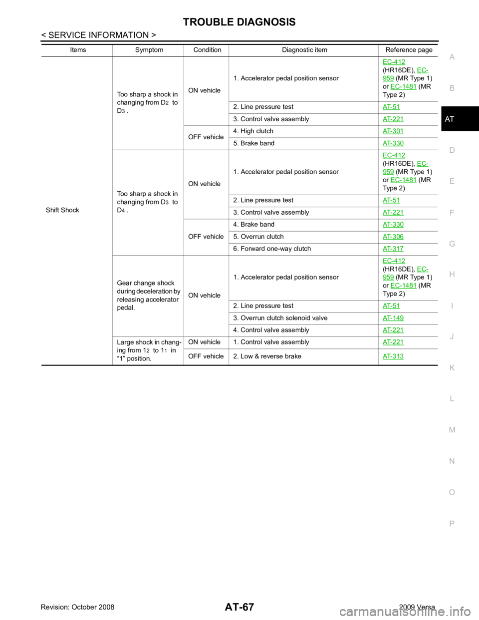
Shift Shock
Too sharp a shock in
changing from D 2
to
D 3 . ON vehicle
1. Accelerator pedal position sensor EC-412
(HR16DE), EC- 959 (MR Type 1)
or EC-1481 (MR
Type 2)
2. Line pressure test AT-51 3. Control valve assembly
AT-221 OFF vehicle
4. High clutch
AT-301 5. Brake band
AT-330Too sharp a shock in
changing from D 3 to
D 4 . ON vehicle
1. Accelerator pedal position sensor EC-412
(HR16DE), EC- 959 (MR Type 1)
or EC-1481 (MR
Type 2)
2. Line pressure test AT-51 3. Control valve assembly
AT-221 OFF vehicle
4. Brake band
AT-330 5. Overrun clutch
AT-306 6. Forward one-way clutch
AT-317Gear change shock
during deceleration by
releasing accelerator
pedal. ON vehicle1. Accelerator pedal position sensor
EC-412
(HR16DE), EC- 959 (MR Type 1)
or EC-1481 (MR
Type 2)
2. Line pressure test AT-51 3. Overrun clutch solenoid valve
AT-149 4. Control valve assembly
AT-221Large shock in chang-
ing from 1 2 to 1 1 in
“1” position. ON vehicle 1. Control valve assembly
AT-221OFF vehicle 2. Low & reverse brake
AT-313Items Symptom Condition Diagnostic item Reference page
Page 73 of 4331
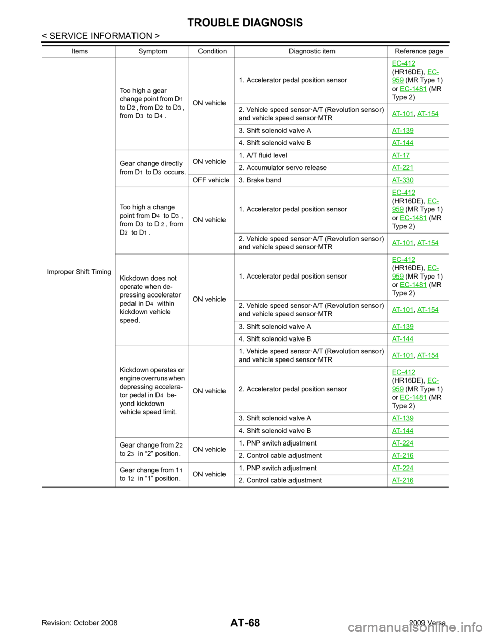
(HR16DE), EC- 959 (MR Type 1)
or EC-1481 (MR
Type 2)
2. Vehicle speed sensor·A/T (Revolution sensor)
and vehicle speed sensor·MTR AT-101 ,
AT-154 3. Shift solenoid valve A
AT-139 4. Shift solenoid valve B
AT-144Gear change directly
from D 1 to D 3 occurs. ON vehicle
1. A/T fluid level
AT-17 2. Accumulator servo release
AT-221 OFF vehicle 3. Brake band
AT-330Too high a change
point from D 4 to D 3 ,
from D 3 to D 2 , from
D 2 to D 1 . ON vehicle
1. Accelerator pedal position sensor EC-412
(HR16DE), EC- 959 (MR Type 1)
or EC-1481 (MR
Type 2)
2. Vehicle speed sensor·A/T (Revolution sensor)
and vehicle speed sensor·MTR AT-101 ,
AT-154 Kickdown does not
operate when de-
pressing accelerator
pedal in D 4 within
kickdown vehicle
speed. ON vehicle1. Accelerator pedal position sensor
EC-412
(HR16DE), EC- 959 (MR Type 1)
or EC-1481 (MR
Type 2)
2. Vehicle speed sensor·A/T (Revolution sensor)
and vehicle speed sensor·MTR AT-101 ,
AT-154 3. Shift solenoid valve A
AT-139 4. Shift solenoid valve B
AT-144Kickdown operates or
engine overruns when
depressing accelera-
tor pedal in D 4 be-
yond kickdown
vehicle speed limit. ON vehicle1. Vehicle speed sensor·A/T (Revolution sensor)
and vehicle speed sensor·MTR AT-101 ,
AT-154 2. Accelerator pedal position sensor
EC-412
(HR16DE), EC- 959 (MR Type 1)
or EC-1481 (MR
Type 2)
3. Shift solenoid valve A AT-139 4. Shift solenoid valve B
AT-144Gear change from 2
2
to 2 3 in “2” position. ON vehicle1. PNP switch adjustment
AT-224 2. Control cable adjustment
AT-216Gear change from 1
1
to 1 2 in “1” position. ON vehicle1. PNP switch adjustment
AT-224 2. Control cable adjustment
AT-216Items Symptom Condition Diagnostic item Reference page