2009 NISSAN ARMADA battery
[x] Cancel search: batteryPage 403 of 465
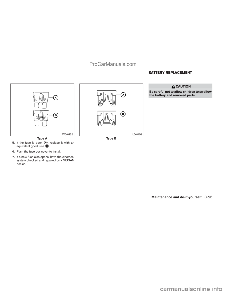
5. If the fuse is opensA, replace it with an
equivalent good fuse
sB.
6. Push the fuse box cover to install.
7. If a new fuse also opens, have the electrical
system checked and repaired by a NISSAN
dealer.
CAUTION
Be careful not to allow children to swallow
the battery and removed parts.
Type A
WDI0452
Type B
LDI0456
BATTERY REPLACEMENT
Maintenance and do-it-yourself8-25
ZREVIEW COPYÐ2009 Armada(wzw)
Owners ManualÐUSA_English(nna)
02/26/08Ðdebbie
X
ProCarManuals.com
Page 404 of 465
KEYFOB
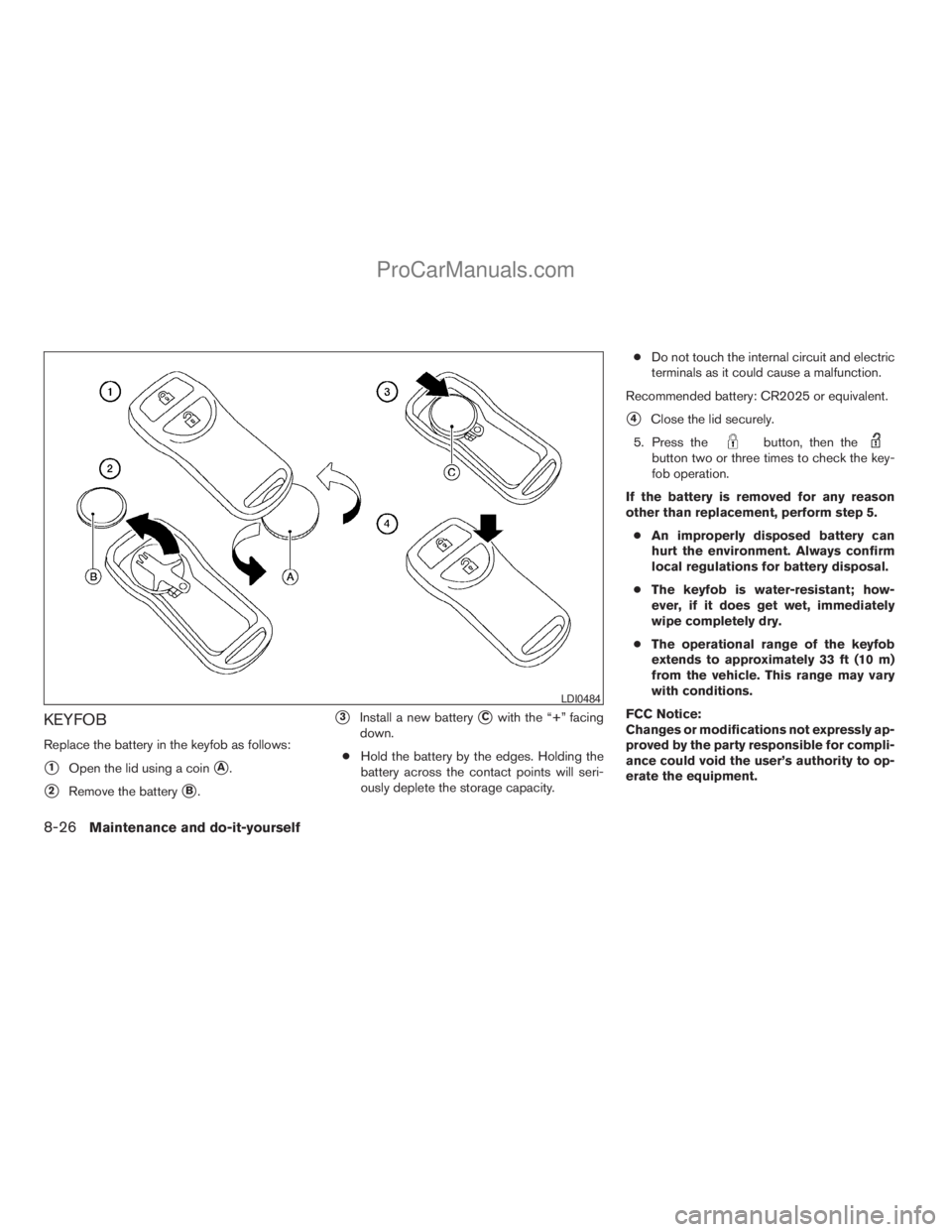
Replace the battery in the keyfob as follows:
s1Open the lid using a coinsA.
s2Remove the batterysB.
s3Install a new batterysCwith the “+” facing
down.
cHold the battery by the edges. Holding the
battery across the contact points will seri-
ously deplete the storage capacity.cDo not touch the internal circuit and electric
terminals as it could cause a malfunction.
Recommended battery: CR2025 or equivalent.
s4Close the lid securely.
5. Press the
button, then thebutton two or three times to check the key-
fob operation.
If the battery is removed for any reason
other than replacement, perform step 5.
cAn improperly disposed battery can
hurt the environment. Always confirm
local regulations for battery disposal.
cThe keyfob is water-resistant; how-
ever, if it does get wet, immediately
wipe completely dry.
cThe operational range of the keyfob
extends to approximately 33 ft (10 m)
from the vehicle. This range may vary
with conditions.
FCC Notice:
Changes or modifications not expressly ap-
proved by the party responsible for compli-
ance could void the user’s authority to op-
erate the equipment.
LDI0484
8-26Maintenance and do-it-yourself
ZREVIEW COPYÐ2009 Armada(wzw)
Owners ManualÐUSA_English(nna)
02/26/08Ðdebbie
X
ProCarManuals.com
Page 405 of 465
This device complies with Part 15 of the
FCC Rules and RSS-210 of Industry
Canada.
Operation is subject to the following two
conditions: (1) This device may not cause
harmful interference, and (2) this device
must accept any interference received, in-
cluding interference that may cause undes-
ired operation of the device.INTELLIGENT KEY
Replace the battery in the Intelligent Key as fol-
lows:
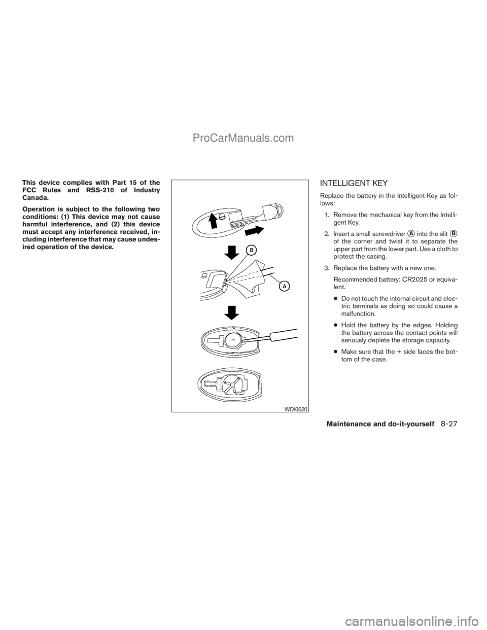
1. Remove the mechanical key from the Intelli-
gent Key.
2. Insert a small screwdriver
sAinto the slitsB
of the corner and twist it to separate the
upper part from the lower part. Use a cloth to
protect the casing.
3. Replace the battery with a new one.
Recommended battery: CR2025 or equiva-
lent.
cDo not touch the internal circuit and elec-
tric terminals as doing so could cause a
malfunction.
cHold the battery by the edges. Holding
the battery across the contact points will
seriously deplete the storage capacity.
cMake sure that the + side faces the bot-
tom of the case.
WDI0620
Maintenance and do-it-yourself8-27
ZREVIEW COPYÐ2009 Armada(wzw)
Owners ManualÐUSA_English(nna)
02/26/08Ðdebbie
X
ProCarManuals.com
Page 407 of 465
cUse the same number and wattage as
originally installed:
Low beam:
Wattage: 51
Bulb no.: 9006*
High beam:
Wattage: 60
Bulb no.: 9005*
*: Always check with the Parts Depart-
ment at a NISSAN dealer for the latest
parts information.
cDo not leave the bulb out of the head-
light reflector for a long period of time
as dust, moisture and smoke may enter
the headlight body and affect the per-
formance of the headlight.
cAiming is not necessary after replacing
the bulb. When aiming adjustment is
necessary, contact a NISSAN dealer.
Fog may temporarily form inside the lens of the
exterior lights in the rain or in a car wash. A
temperature difference between the inside and
the outside of the lens causes the fog. This is not
a malfunction. If large drops of water collect
inside the lens, contact a NISSAN dealer.FOG LIGHTS (if so equipped)
Replacing the fog light bulb
CAUTION
cHigh pressure halogen gas is sealed
inside the halogen bulb. The bulb may
break if the glass envelope is scratched
or the bulb is dropped.
cWhen handling the bulb, do not touch
the glass envelope.
cUse the same number and wattage as
originally installed:
Wattage 37.5 Bulb No. 899*
*: Always check with the Parts Depart-
ment at a NISSAN dealer for the latest
parts information.
cDo not leave the bulb out of the fog light
for a long period of time as dust, mois-
ture and smoke may enter the fog light
body and affect the performance of the
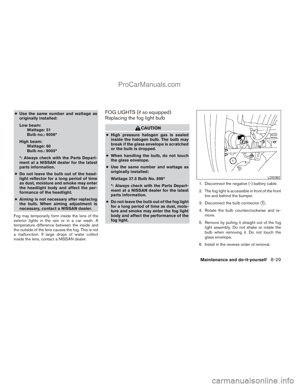
fog light.1. Disconnect the negative (-) battery cable.
2. The fog light is accessible in front of the front
tire and behind the bumper.
3. Disconnect the bulb connector
s1.
4. Rotate the bulb counterclockwise and re-
move.
5. Remove by pulling it straight out of the fog
light assembly. Do not shake or rotate the
bulb when removing it. Do not touch the
glass envelope.
6. Install in the reverse order of removal.
LDI0382
Maintenance and do-it-yourself8-29
ZREVIEW COPYÐ2009 Armada(wzw)
Owners ManualÐUSA_English(nna)
02/26/08Ðdebbie
X
ProCarManuals.com
Page 445 of 465
CAUTION
cSpecial hitches which include frame re-
inforcements are required for towing
above 2,000 lb (907 kg) . Suitable genu-
ine NISSAN hitches, ball mounts and
hitch balls for pickup trucks and sport
utility vehicles are available at a
NISSAN dealer.
cThe hitch should not be attached to or
affect the operation of the impact-
absorbing bumper.
cDo not use axle-mounted hitches.
cDo not modify the vehicle exhaust sys-
tem, brake system, etc. to install a
trailer hitch.
cTo reduce the possibility of additional
damage if your vehicle is struck from
the rear, where practical, remove the
receiver when not in use.
cRegularly check that all trailer hitch
mounting bolts are securely mounted.
cWhen towing with the hitch ball
mounted to the rear bumper, do not
make sharp turns. The trailer may con-
tact the bumper and cause damage to
the bumper or trailer.
Tire pressures
cWhen towing a trailer, inflate the ve-
hicle tires to the recommended cold
tire pressure indicated on the tire
placard.
cTrailer tire condition, size, load rating
and proper inflation pressure should
be in accordance with the trailer and
tire manufacturer’s specifications.
Safety chains
Always use suitable safety chains between your
vehicle and the trailer. The safety chains should
be crossed and should be attached to the hitch,
not to the vehicle bumper or axle. The safety
chains can be attached to the bumper if the hitch
ball is mounted to the bumper. Be sure to leave
enough slack in the chains to permit turning
corners.
Trailer lights
CAUTION
When splicing into the vehicle electrical
system, a commercially available power-
type module/converter must be used to
provide power for all trailer lighting. This
unit uses the vehicle battery as a direct
power source for all trailer lights while
using the vehicle tail light, stoplight and
turn signal circuits as a signal source. The
module/converter must draw no more
that 15 milliamps from the stop and tail
lamp circuits. Using a module/converter
that exceeds these power requirements
may damage the vehicle’s electrical sys-
tem. See a reputable trailer dealer to ob-
tain the proper equipment and to have it
installed.
Trailer lights should comply with federal and/or
local regulations. For assistance in hooking up
trailer lights, contact a NISSAN dealer or repu-
table trailer dealer. Vehicles equipped with the
optional trailer tow package are equipped with a
7-pin trailer harness connector. If your trailer is
equipped with a flat 4-pin connector, an adapter
will be needed to connect the trailer lights to the
vehicle. Adapters are available at NISSAN deal-
ers as well as auto parts stores and hitch retail-
ers.
Technical and consumer information9-23
ZREVIEW COPYÐ2009 Armada(wzw)
Owners ManualÐUSA_English(nna)
02/27/08Ðtbrooks
X
ProCarManuals.com
Page 447 of 465
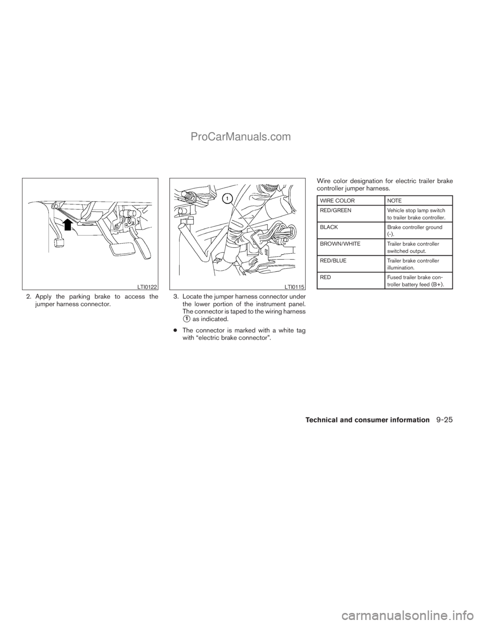
2. Apply the parking brake to access the
jumper harness connector.3. Locate the jumper harness connector under
the lower portion of the instrument panel.
The connector is taped to the wiring harness
s1as indicated.
cThe connector is marked with a white tag
with “electric brake connector”.Wire color designation for electric trailer brake
controller jumper harness.
WIRE COLOR NOTE
RED/GREEN Vehicle stop lamp switch
to trailer brake controller.
BLACK Brake controller ground
(-) .
BROWN/WHITE Trailer brake controller
switched output.
RED/BLUE Trailer brake controller
illumination.
RED Fused trailer brake con-
troller battery feed (B+) .
LTI0122LTI0115
Technical and consumer information9-25
ZREVIEW COPYÐ2009 Armada(wzw)
Owners ManualÐUSA_English(nna)
02/26/08Ðdebbie
X
ProCarManuals.com
Page 453 of 465
If you believe that your vehicle has a de-
fect which could cause a crash or could
cause injury or death, you should immedi-
ately inform the National Highway Traffic
Safety Administration (NHTSA) in addi-
tion to notifying NISSAN.
If NHTSA receives similar complaints, it
may open an investigation, and if it finds
that a safety defect exists in a group of
vehicles, it may order a recall and remedy
campaign. However, NHTSA cannot be-
come involved in individual problems be-
tween you, your dealer, or NISSAN.
To contact NHTSA, you may call the Ve-
hicle Safety Hotline toll-free at 1-888-
327-4236 (TTY: 1-800-424-9153); go
to http://www.safercar.gov; or write to:
Administrator, NHTSA, 400 Seventh
Street, SW., Washington, D.C. 20590.
You can also obtain other information
about motor vehicle safety from
http://www.safercar.gov.
You may notify NISSAN by contacting our
Consumer Affairs Department, toll-free, at
1-800-NISSAN-1.Due to legal requirements in some states and
Canadian Provinces, your vehicle may be re-
quired to be in what is called the “ready condi-
tion” for an Inspection/Maintenance (I/M) test of
the emission control system.
The vehicle is set to the “ready condition” when it
is driven through certain driving patterns. Usually,
the ready condition can be obtained by ordinary
usage of the vehicle.
If a powertrain system component is repaired or
the battery is disconnected, the vehicle may be
reset to a “not ready” condition. Before taking the
I/M test, check the vehicle’s
inspection/maintenance test readiness condi-
tion. Turn the ignition switch ON without starting
the engine. If the Malfunction Indicator Light
(MIL) comes on steady for 20 seconds and then
blinks for 10 seconds , the I/M test condition is
“not ready”. If the MIL does not blink after 20 sec-
onds, the I/M test condition is “ready”. If the MIL
indicates the vehicle is in a “not ready” condition,
drive the vehicle through the following pattern to
set the vehicle to the ready condition. If you
cannot or do not want to perform the driving
pattern, a NISSAN dealer can conduct it for you.WARNING
Always drive the vehicle in a safe and
prudent manner according to traffic con-
ditions and obey all traffic laws.
1. Start the engine when the engine coolant
temperature gauge needle points to C. Al-
low the engine to idle until the gauge needle
points between the C and H (normal oper-
ating temperature) .
2. Accelerate the vehicle to 55 MPH (88 km/h),
then quickly release the accelerator pedal
completely and keep it released for at least
10 seconds.
3. Quickly depress the accelerator pedal for a
moment, then drive the vehicle at a speed of
53 - 60 MPH (86 - 96 km/h) for at least
9 minutes.
4. Stop the vehicle.
5. Accelerate the vehicle to 35 MPH (55 km/h)
and maintain the speed for 20 seconds.
6. Repeat steps 4 through 5 at least 10 times.
7. Accelerate the vehicle to 55 MPH (88 km/h)
and maintain the speed for at least 3 min-
utes.
REPORTING SAFETY DEFECTS (US
only)READINESS FOR INSPECTION/
MAINTENANCE (I/M) TEST
Technical and consumer information9-31
ZREVIEW COPYÐ2009 Armada(wzw)
Owners ManualÐUSA_English(nna)
02/26/08Ðdebbie
X
ProCarManuals.com
Page 457 of 465
10 Index
4WD warning light...............2-16
A
Active Head Restraint..............1-9
Adjusting pedal position............3-28
Air bag (See supplemental restraint
system).....................1-49
Air bag system
Front (See supplemental front impact
air bag system)...............1-57
Air bag warning labels.............1-64
Air bag warning light...........1-64, 2-18
Air cleaner housing filter............8-17
Air conditioner
Air conditioner service...........4-39
Air conditioner specification label.....9-12
Air conditioner system refrigerant and
oil recommendations.............9-7
Heater and air conditioner controls. . . .4-36
Rear seat air conditioner..........4-38
Servicing air conditioner..........4-39
Alarm system
(See vehicle security system).........2-27
Anchor point locations.............1-32
Antenna.....................4-75
Anti-lock brake warning light......2-13, 2-14
Anti-lock Braking System (ABS)........5-29
Audible reminders................2-20
Audio system..................4-39
Compact Disc (CD) changer.......4-50Compact disc (CD) player.........4-58
Audio System
CompactFlash (CF) player.........4-60
Audio system
FM/AM/SAT radio with compact disc
(CD) changer................4-47
FM/AM/SAT radio with compact disc
(CD) player.................4-55
Audio System
Music Box hard-disk drive audio
system....................4-62
Audio system
Radio....................4-39
Rear audio controls.............4-74
Audio System
Settings................4-47, 4-55
Audio system
Steering wheel audio control switch. . . .4-73
Autolight switch.................2-33
Automatic
Automatic drive positioner.........3-32
Automatic power window switch.....2-53
Automatic transmission position indicator
light.....................2-27
Driving with automatic transmission. . . .5-14
Transmission selector lever lock
release....................5-16
Automatic anti-glare inside mirror.......3-29
Automatic transmission fluid temperature
gauge.......................2-9
AUX jack.................4-53, 4-60B
Battery......................8-13
Charge warning light............2-15
Before starting the engine...........5-12
Belt (See drive belt)..............8-15
Block heater
Engine....................5-35
BluetoothThands-free phone
system..................4-92, 4-107
Booster seats..................1-44
Brake
Anti-lock Braking System (ABS)......5-29
Brake fluid..................8-12
Brake light (See stop light).........8-30
Brake system................5-28
Brake warning light.............2-14
Brake wear indicators........2-20, 8-22
Parking brake operation..........5-17
Self-adjusting brakes............8-22
Brakes......................8-22
Break-in schedule................5-19
Brightness control
Instrument panel..............2-35
Brightness/contrast button.......4-16, 4-32
Bulb check/instrument panel..........2-13
Bulb replacement................8-30
ZREVIEW COPYÐ2009 Armada(wzw)
Owners ManualÐUSA_English(nna)
02/26/08Ðdebbie
X
ProCarManuals.com