2009 NISSAN ALTIMA HYBRID trunk
[x] Cancel search: trunkPage 7 of 22
- 7 -
Exterior
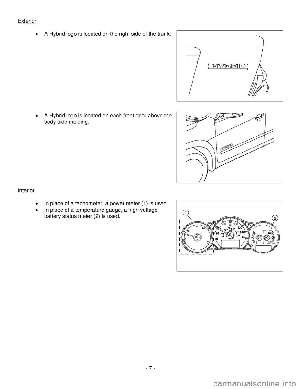
• A Hybrid logo is located on the right side of the trunk.
• A Hybrid logo is located on each front door above the
body side molding.
Interior
• In place of a tachometer, a power meter (1) is used.
• In place of a temperature gauge, a high voltage
battery status meter (2) is used.
Page 8 of 22
- 8 -
Hybrid System
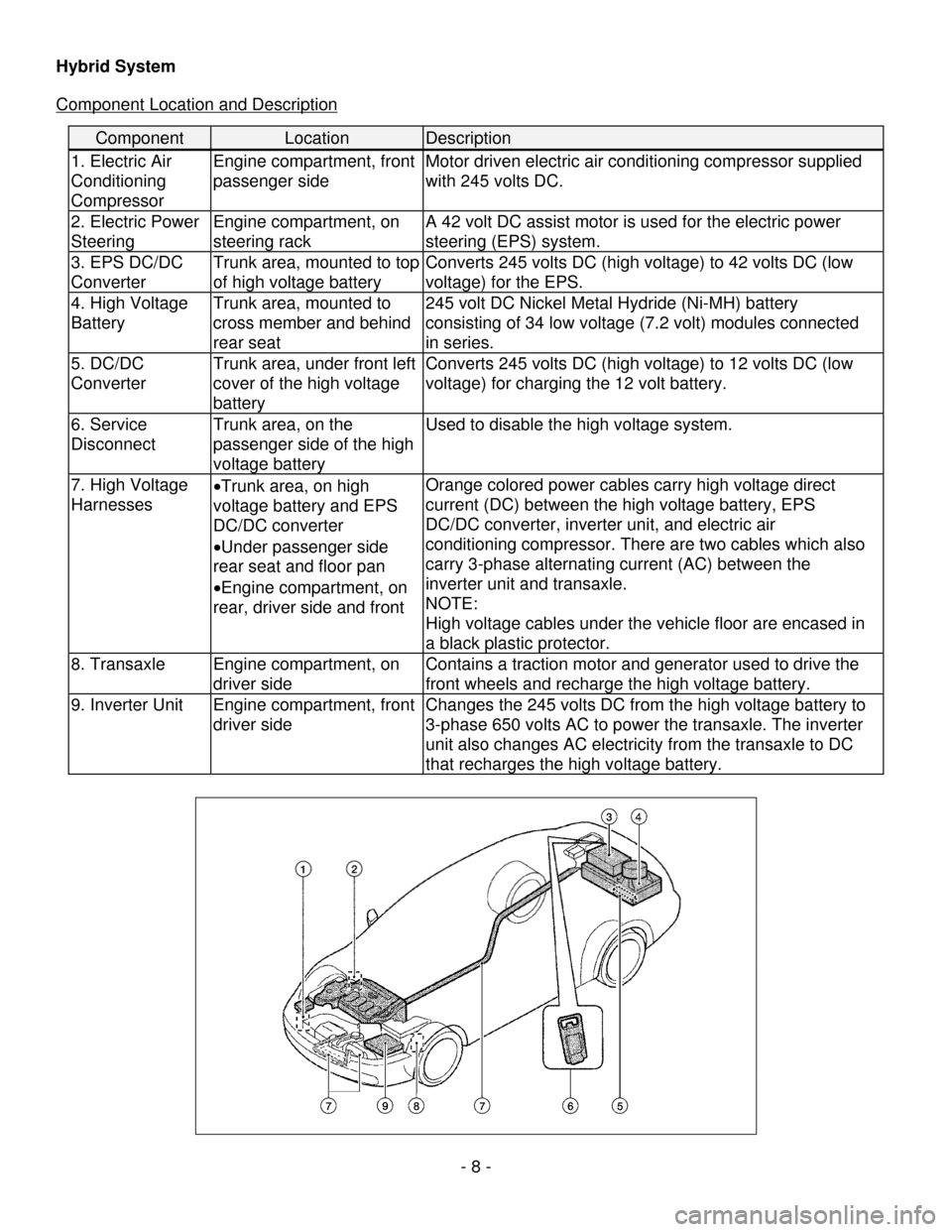
Component Location and Description
Component Location Description
1. Electric Air
Conditioning
Compressor
Engine compartment, front
passenger side
Motor driven electric air conditioning compressor supplied
with 245 volts DC.
2. Electric Power
Steering Engine compartment, on
steering rack A 42 volt DC assist motor is used for the electric power
steering (EPS) system.
3. EPS DC/DC
Converter Trunk area, mounted to top
of high voltage battery Converts 245 volts DC (high voltage) to 42 volts DC (low
voltage) for the EPS.
4. High Voltage
Battery Trunk area, mounted to
cross member and behind
rear seat 245 volt DC Nickel Metal Hydride (Ni-MH) battery
consisting of 34 low voltage (7.2 volt) modules connected
in series.
5. DC/DC
Converter
Trunk area, under front left
cover of the high voltage
battery Converts 245 volts DC (high voltage) to 12 volts DC (low
voltage) for charging the 12 volt battery.
6. Service
Disconnect
Trunk area, on the
passenger side of the high
voltage battery Used to disable the high voltage system.
7. High Voltage
Harnesses
•
Trunk area, on high
voltage battery and EPS
DC/DC converter
• Under passenger side
rear seat and floor pan
• Engine compartment, on
rear, driver side and front Orange colored power cables carry high voltage direct
current (DC) between the high voltage battery, EPS
DC/DC converter, inverter unit, and electric air
conditioning compressor. There are two cables which also
carry 3-phase alternating current (AC) between the
inverter unit and transaxle.
NOTE:
High voltage cables under the vehicle floor are encased in
a black plastic protector.
8. Transaxle
Engine compartment, on
driver side Contains a traction motor and generator used to drive the
front wheels and recharge the high voltage battery.
9. Inverter Unit Engine compartment, front
driver side Changes the 245 volts DC from the high voltage battery to
3-phase 650 volts AC to power the transaxle. The inverter
unit also changes AC electricity from the transaxle to DC
that recharges the high voltage battery.
Page 9 of 22
- 9 -
Battery Information
The Altima Hybrid utilizes two batteries in order to supply both low and high voltage.
Low Voltage Battery
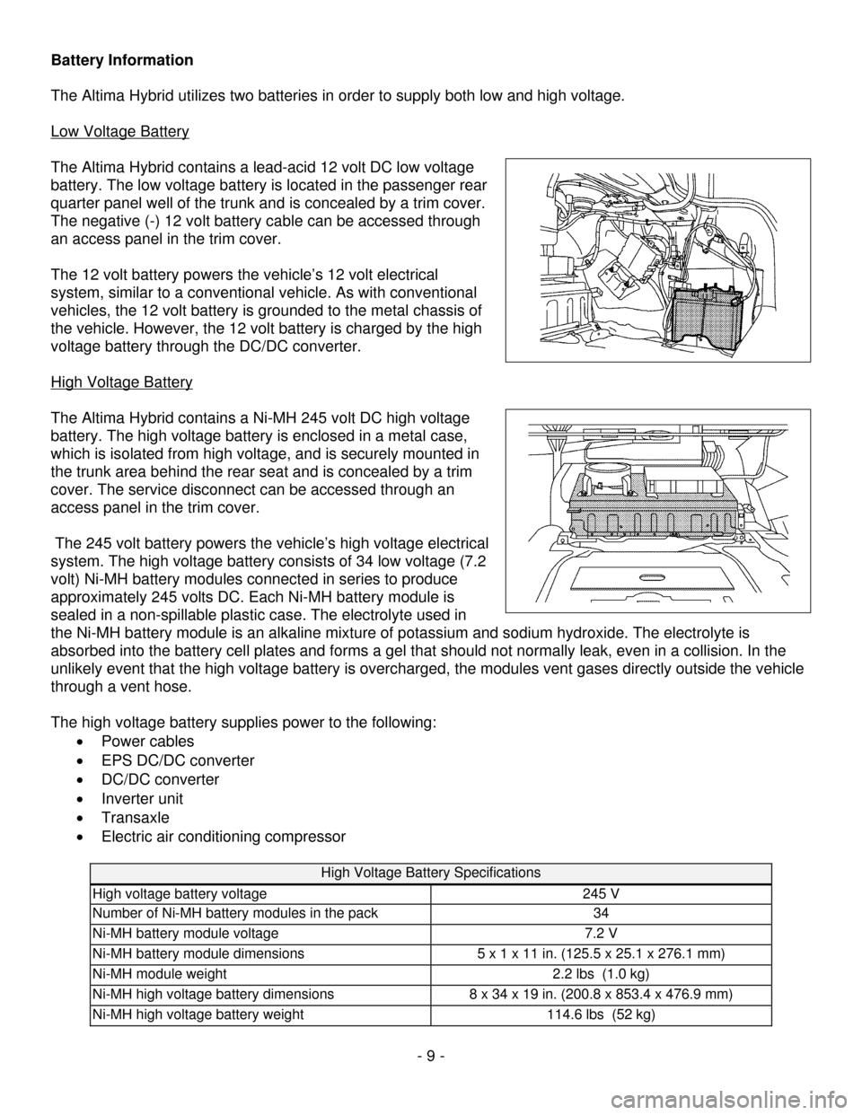
The Altima Hybrid contains a lead-acid 12 volt DC low voltage
battery. The low voltage battery is located in the passenger rear
quarter panel well of the trunk and is concealed by a trim cover.
The negative (-) 12 volt battery cable can be accessed through
an access panel in the trim cover.
The 12 volt battery powers the vehicle’s 12 volt electrical
system, similar to a conventional vehicle. As with conventional
vehicles, the 12 volt battery is grounded to the metal chassis of
the vehicle. However, the 12 volt battery is charged by the high
voltage battery through the DC/DC converter.
High Voltage Battery
The Altima Hybrid contains a Ni-MH 245 volt DC high voltage
battery. The high voltage battery is enclosed in a metal case,
which is isolated from high voltage, and is securely mounted in
the trunk area behind the rear seat and is concealed by a trim
cover. The service disconnect can be accessed through an
access panel in the trim cover.
The 245 volt battery powers the vehicle’s high voltage electrical
system. The high voltage battery consists of 34 low voltage (7.2
volt) Ni-MH battery modules connected in series to produce
approximately 245 volts DC. Each Ni-MH battery module is
sealed in a non-spillable plastic case. The electrolyte used in
the Ni-MH battery module is an alkaline mixture of potassium and sodium hydroxide. The electrolyte is
absorbed into the battery cell plates and forms a gel that should not normally leak, even in a collision. In the
unlikely event that the high voltage battery is overcharged, the modules vent gases directly outside the vehicle
through a vent hose.
The high voltage battery supplies power to the following:
• Power cables
• EPS DC/DC converter
• DC/DC converter
• Inverter unit
• Transaxle
• Electric air conditioning compressor
High Voltage Battery Specifications
High voltage battery voltage 245 V
Number of Ni-MH battery modules in the pack 34
Ni-MH battery module voltage 7.2 V
Ni-MH battery module dimensions 5 x 1 x 11 in. (125.5 x 25.1 x 276.1 mm)
Ni-MH module weight 2.2 lbs (1.0 kg)
Ni-MH high voltage battery dimensions 8 x 34 x 19 in. (200.8 x 853.4 x 476.9 mm)
Ni-MH high voltage battery weight 114.6 lbs (52 kg)
Page 16 of 22
- 16 -
Dismantling the High Voltage System
Dismantling of the Altima Hybrid may be performed like conventional Niss\
an vehicles, except as noted in these
guidelines.
Service Disconnect
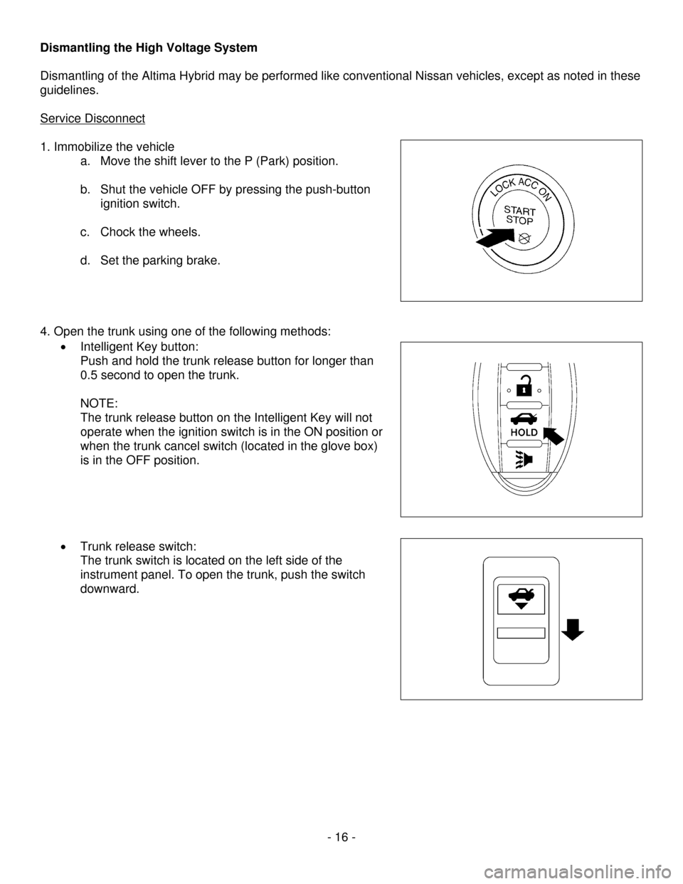
1. Immobilize the vehicle a. Move the shift lever to the P (Park) position.
b. Shut the vehicle OFF by pressing the push-button
ignition switch.
c. Chock the wheels.
d. Set the parking brake.
4. Open the trunk using one of the following methods:
• Intelligent Key button:
Push and hold the trunk release button for longer than
0.5 second to open the trunk.
NOTE:
The trunk release button on the Intelligent Key will not
operate when the ignition switch is in the ON position or
when the trunk cancel switch (located in the glove box)
is in the OFF position.
• Trunk release switch:
The trunk switch is located on the left side of the
instrument panel. To open the trunk, push the switch
downward.
Page 17 of 22
- 17 -
•
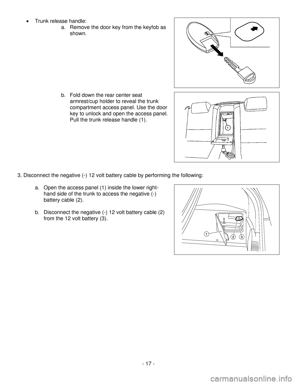
Trunk release handle:
a. Remove the door key from the keyfob as
shown.
b. Fold down the rear center seat
armrest/cup holder to reveal the trunk
compartment access panel. Use the door
key to unlock and open the access panel.
Pull the trunk release handle (1).
3. Disconnect the negative (-) 12 volt battery cable by performing the following:
a. Open the access panel (1) inside the lower right-
hand side of the trunk to access the negative (-)
battery cable (2).
b. Disconnect the negative (-) 12 volt battery cable (2)
from the 12 volt battery (3).
Page 18 of 22
- 18 -
DANGER:
•
The high voltage system may remain powered for up to 10 minutes after the vehicle is disabled.
•
To prevent serious injury or death from electrical shock avoid touching, cutting, or breaching any
orange high voltage power cable or high voltage component while the system discharges.
WARNING:
• The SRS may remain powered for up to 3 minutes after the vehicle is disabled.
• To prevent serious injury or death from unintentional SRS deployment, avoid crushing, cutting, or
breaching the SRS components.
• If the disabling procedures cannot be performed completely, proceed with caution as there is no
assurance that the high voltage electrical system, SRS, or fuel pump are disabled.
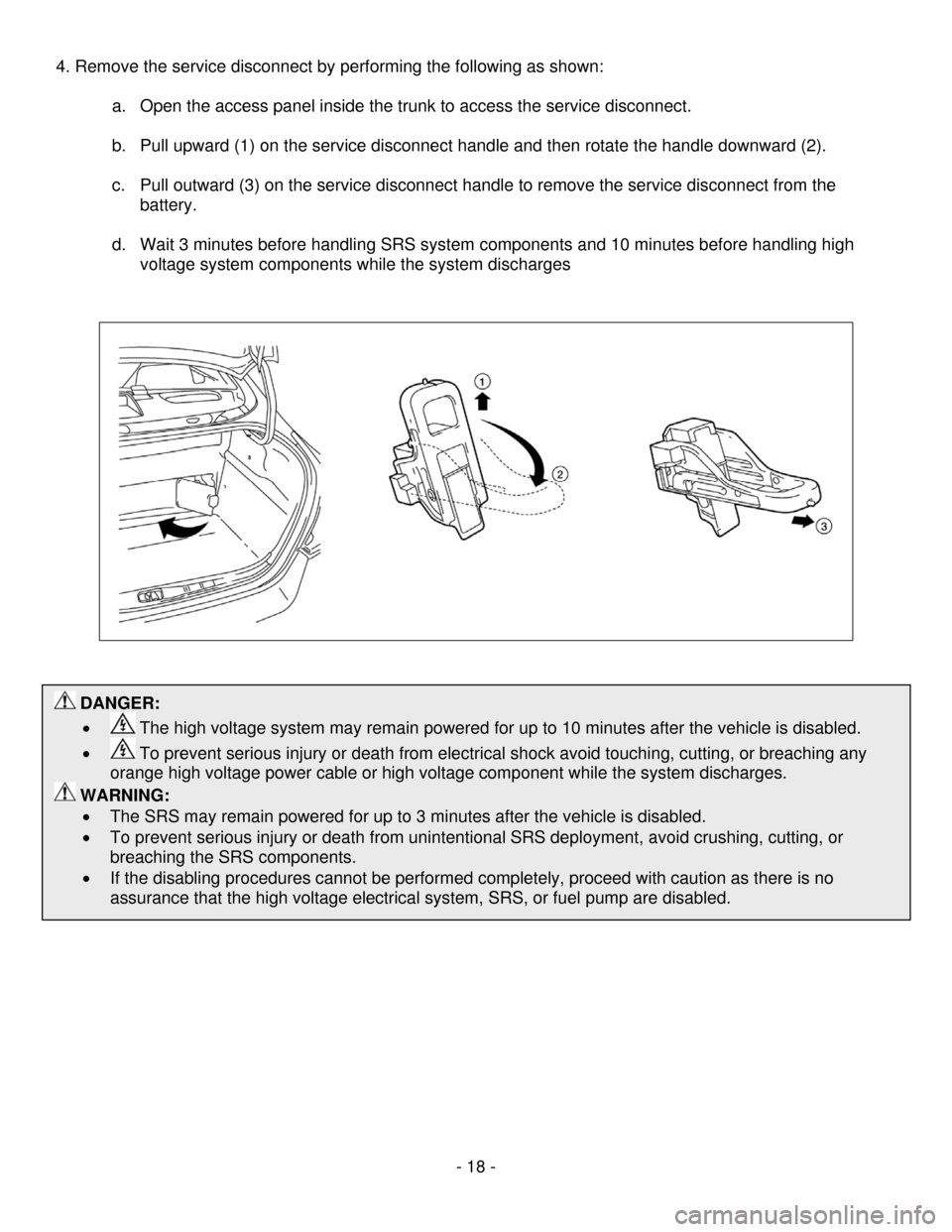
4. Remove the service disconnect by performing the following as shown:
a. Open the access panel inside the trunk to access the service disconnect.
b. Pull upward (1) on the service disconnect handle and then rotate the handle downward (2).
c. Pull outward (3) on the service disconnect handle to remove the service disconnect from the
battery.
d. Wait 3 minutes before handling SRS system components and 10 minutes before handling high
voltage system components while the system discharges
Page 20 of 22
Removal of HV Battery
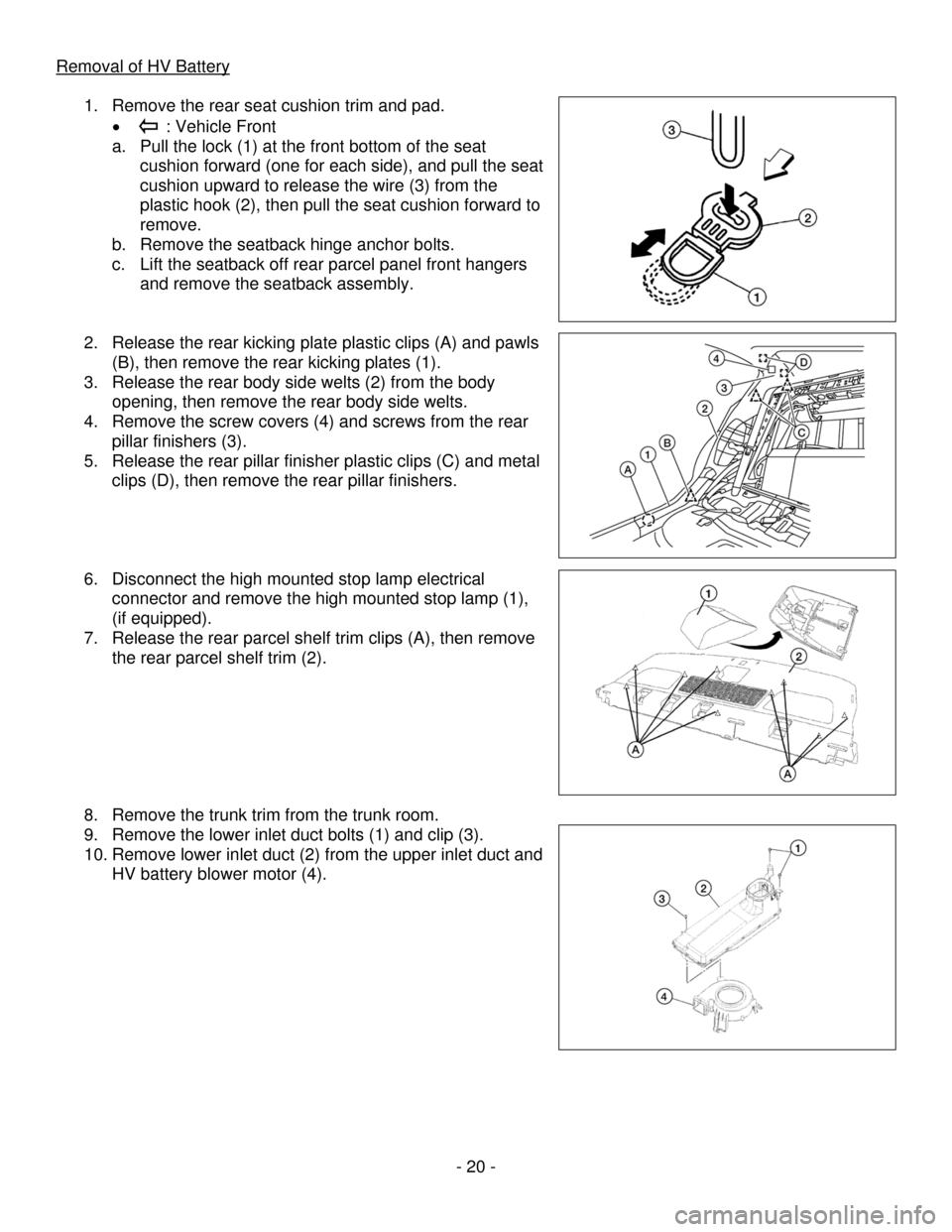
1. Remove the rear seat cushion trim and pad.
• : Vehicle Front
a. Pull the lock (1) at the front bottom of the seat
cushion forward (one for each side), and pull the seat
cushion upward to release the wire (3) from the
plastic hook (2), then pull the seat cushion forward to
remove.
b. Remove the seatback hinge anchor bolts.
c. Lift the seatback off rear parcel panel front hangers
and remove the seatback assembly.
2. Release the rear kicking plate plastic clips (A) and pawls
(B), then remove the rear kicking plates (1).
3. Release the rear body side welts (2) from the body
opening, then remove the rear body side welts.
4. Remove the screw covers (4) and screws from the rear
pillar finishers (3).
5. Release the rear pillar finisher plastic clips (C) and metal
clips (D), then remove the rear pillar finishers.
6. Disconnect the high mounted stop lamp electrical
connector and remove the high mounted stop lamp (1),
(if equipped).
7. Release the rear parcel shelf trim clips (A), then remove
the rear parcel shelf trim (2).
8. Remove the trunk trim from the trunk room.
9. Remove the lower inlet duct bolts (1) and clip (3).
10. Remove lower inlet duct (2) from the upper inlet duct and
HV battery blower motor (4).
- 20 -